Generator Control System Test: 3.0CL
- Disconnect generator 4-pin connector. Start engine. Turn on headlights (high beam). Use DVOM to measure voltage between generator 4-pin connector terminal No. 2 (White/Green wire) and battery positive terminal. See Figure. If reading is one volt or less, go to step 3). If reading is greater than one volt, go to next step.
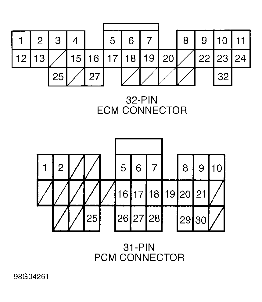
- Turn headlights and ignition off. Disconnect 31-pin connector from Powertrain Control Module (PCM), located behind right kick panel. Use DVOM and check continuity of White/Green wire between ground and ECM connector terminal No. 2. See Fig 1. If continuity exists, repair short to ground in White/Green wire. If continuity does not exist, install known good PCM and recheck system. Replace PCM if necessary.
- Turn headlights and ignition switch to OFF position. Disconnect 31-pin connector from PCM, located behind right kick panel. Use DVOM and check continuity of White/Green wire between PCM connector terminal No. 2 and 4-pin generator connector terminal No. 2. See Figure and Fig 1. If continuity does not exist, repair open in White/Green wire. If continuity exists, test alternator and regulator. See GENERATOR/REGULATOR OUTPUT TEST .
 Courtesy of AMERICAN HONDA MOTOR CO., INC.