DTC P1457 EVAP Control System
- Disconnect vacuum hose from EVAP purge control solenoid valve "A". Connect vacuum pump to disconnected hose. Connect jumper wire between PCM 32-pin connector terminal No. 6 (Red/Yellow wire) and ground. Turn ignition on. Apply vacuum to hose. If valve holds vacuum, go to next step. If valve does not hold vacuum, EVAP purge control solenoid valve is okay. Go to step 4.
- Turn ignition off. Disconnect EVAP purge control solenoid valve 2-pin connector. Measure continuity between EVAP purge control solenoid valve 2-pin connector terminal No. 2 (Red/Yellow wire) and ground. If continuity is present, go to next step. If continuity is not present, repair open circuit in Red/Yellow wire.
- Turn ignition on. Measure voltage between EVAP purge control solenoid valve 2-pin connector terminal No. 1 (Black/Yellow wire) and ground. If battery voltage is present, replace EVAP purge control solenoid valve. If battery voltage is not present, repair open circuit in wiring between EVAP purge control solenoid valve and No. 6 (15-amp) PCM fuse.
- Disconnect vacuum hose from EVAP 2-way valve. Connect a vacuum pump to disconnected hose. Turn ignition on. Apply vacuum to hose. If valve does not hold vacuum, go to next step. If valve holds vacuum, EVAP by-pass solenoid valve/EVAP 2-way valve is okay. Go to step 7.
- Turn ignition off. Disconnect EVAP by-pass solenoid valve 2-pin connector. Measure continuity between EVAP by-pass solenoid valve 2-pin connector terminal No. 2 (Light Green/White wire) and ground. If continuity is present, go to next step. If continuity is not present, replace EVAP by-pass solenoid valve and "O" rings.
- Disconnect PCM 32-pin connector. Measure continuity between EVAP by-pass solenoid valve 2-pin connector terminal No. 2 (Light Green/White wire) and ground. If continuity is present, repair short circuit in wiring between EVAP by-pass solenoid valve and PCM. If continuity is not present, replace PCM.
- Disconnect vacuum hose from EVAP control canister vent filter. Connect vacuum pump to disconnected hose. Connect jumper wire between PCM 32-pin connector terminal No. 4 (Light Green/White wire) and ground. Turn ignition on. Apply vacuum. If valve does not hold vacuum, go to next step. If valve holds vacuum, EVAP canister vent shut valve is okay. Go to step 10.
- Turn ignition off. Disconnect EVAP control canister vent shut valve 2-pin connector. Measure continuity between EVAP control canister vent shut valve 2-pin connector terminal No. 2 (Light Green/White wire) and ground. If continuity is present, go to next step. If continuity is not present, repair open circuit in Light Green/White wire between EVAP control canister vent shut valve and PCM.
- Turn ignition on. Measure voltage between EVAP control canister vent shut valve 2-pin connector terminal No. 1 (Black/Yellow wire) and ground. If battery voltage is present, replace EVAP control canister vent shut valve. If battery voltage is not present, repair open circuit in Black/Yellow wire between EVAP control canister vent shut valve and No. 6 (15-amp) PCM fuse.
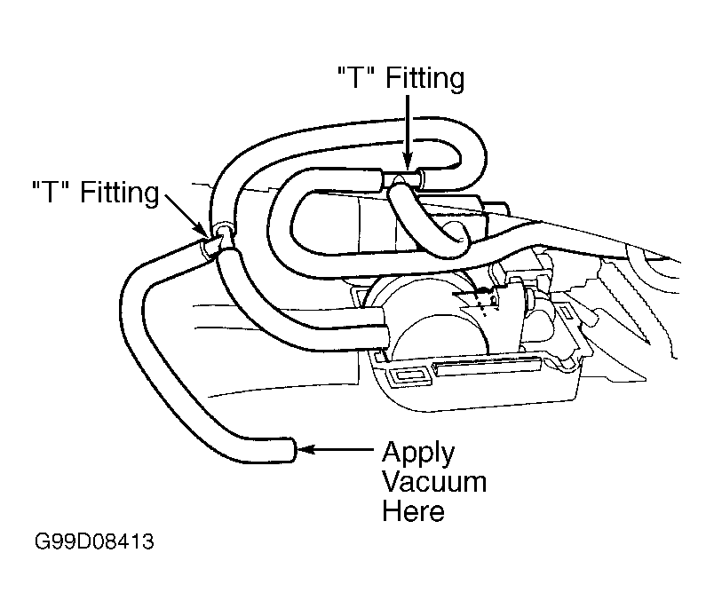
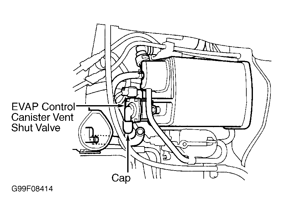
- Turn ignition off. Connect two 3-way "T" fittings into vacuum hose from EVAP control canister to EVAP 2-way valve. See Fig 1. Connect fuel tank pressure sensor to one "T" fitting, and vacuum pump to other "T" fitting. Remove vent hose from EVAP control canister vent shut valve "A". Cap port to seal fresh air vent for EVAP control canister. See Fig 2. Turn ignition on. Measure voltage between PCM 32-pin connector terminal No. 29 (Light Green wire) and PCM 31-pin connector terminal No. 18 (Green/Yellow wire) while slowly applying vacuum. Continue to pump vacuum until voltage drops to about 1.5 volts. Ensure engine coolant temperature is greater than 95°F (35C°) and vacuum pump has no leak. If voltage does not drop to 1.5 volts and hold for at least 20 seconds, go to next step. If voltage drops to 1.5 volts and holds for at least 20 seconds, check EVAP control canister vent shut valve line and connections. Repair as necessary.
 Courtesy of AMERICAN HONDA MOTOR CO., INC.
 Courtesy of AMERICAN HONDA MOTOR CO., INC.
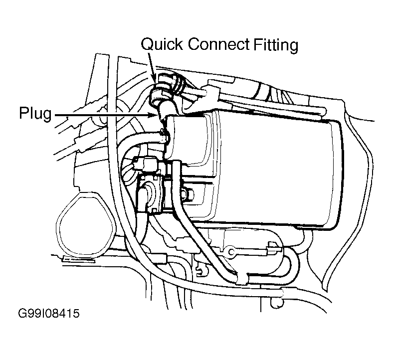
- Turn ignition off. Disconnect quick-connect fitting from EVAP control canister. Plug canister port. See Fig 3. Turn ignition on. Measure voltage between PCM 32-pin connector terminal No. 29 (Light Green wire) and PCM 31-pin connector terminal No. 18 (Green/Black wire) while slowly pumping vacuum pump. Continue to pump vacuum until voltage drops to about 1.5 volts. Ensure engine temperature is greater than 95°F (35°C) and vacuum pump has no leak. Check voltage for 20 seconds. If voltage does not drop to 1.5 volts and hold for at least 20 seconds, go to next step. If voltage drops to 1.5 volts and holds for at least 20 seconds, check EVAP control canister vent shut valve line and connections. Repair as necessary.
 Courtesy of AMERICAN HONDA MOTOR CO., INC.
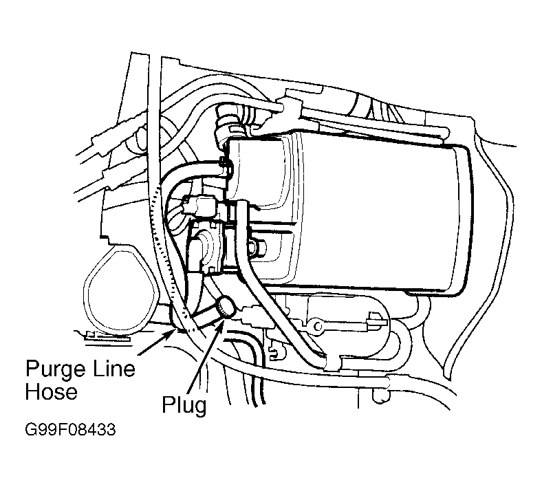
- Turn ignition off. Disconnect purge line hose from canister at metal line. Plug disconnected hose. See Fig 4. Turn ignition on. Measure voltage between PCM 32-pin connector terminal No. 29 (Light Green wire) and PCM 31-pin connector terminal No. 18 (Green/Yellow wire) while slowly pumping vacuum pump. Continue to pump vacuum until voltage drops to about 1.5 volts. Ensure engine coolant temperature is greater than 95°F (35C°) and vacuum pump has no leak. Monitor voltage for 20 seconds. If voltage drops to 1.5 volts and holds for at least 20 seconds, check EVAP purge control solenoid valve and connections. Repair as necessary. If EVAP purge control valve and connections are okay, go to next step. If voltage does not drop to 1.5 volts and hold for at least 20 seconds, check EVAP control canister vent shut valve and "O" ring for leakage. If EVAP control canister vent shut valve and "O" ring are okay, replace EVAP control canister.
 Courtesy of AMERICAN HONDA MOTOR CO., INC.
- Remove fuel filler cap. Remove vapor hose from EVAP 2-way valve. Connect "T" fitting to disconnected hose. Connect vacuum pump to one "T" fitting port and vacuum gauge to other "T" fitting port. See Fig 5. Apply vacuum slowly and continuously while observing gauge. If vacuum stabilizes momentarily at .2-.6 in. Hg, go to next step. If vacuum does not stabilize momentarily at .2-.6 in. Hg, replace valve.
 Courtesy of AMERICAN HONDA MOTOR CO., INC.
- Move vacuum pump hose from vacuum fitting to pressure fitting. Move vacuum gauge hose from vacuum side to pressure side. Slowly pressurize vapor line while observing gauge. If pressure stabilizes momentarily at greater than .3 in. Hg, valve is okay. If pressure does not stabilize at greater than .3 in. Hg, replace valve.