Hall Sending Unit (Generator) Check
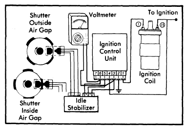
- Reconnect the control unit harness connector to control unit. See Fig 1. Pull back rubber boot on connector. Attach voltmeter positive lead to connector terminal 6 and negative lead to terminal 3. Make sure connector is attached securely to control unit.
 Courtesy of NOT AVAILABLE
- Turn ignition switch "ON". With trigger wheel shutter outside Hall sending unit air gap, check voltage reading. It should be 0.4 volts or less.
- Now turn distributor until trigger wheel shutter is inside Hall sending unit air gap. See inset in Fig 1. Voltmeter reading should increase to 9 volts.
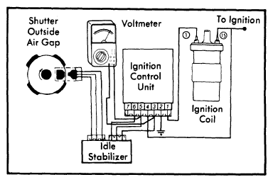
- Connect voltmeter leads in same manner to terminals 3 and 5 of control unit. See Fig 2. Turn ignition switch "ON". Voltage should be a minimum of 7.5 volts.
 Courtesy of NOT AVAILABLE
- If any of the above voltage readings are incorrect, replace the Hall sending unit.