Steering Linkage Outer Tie Rod Replacement
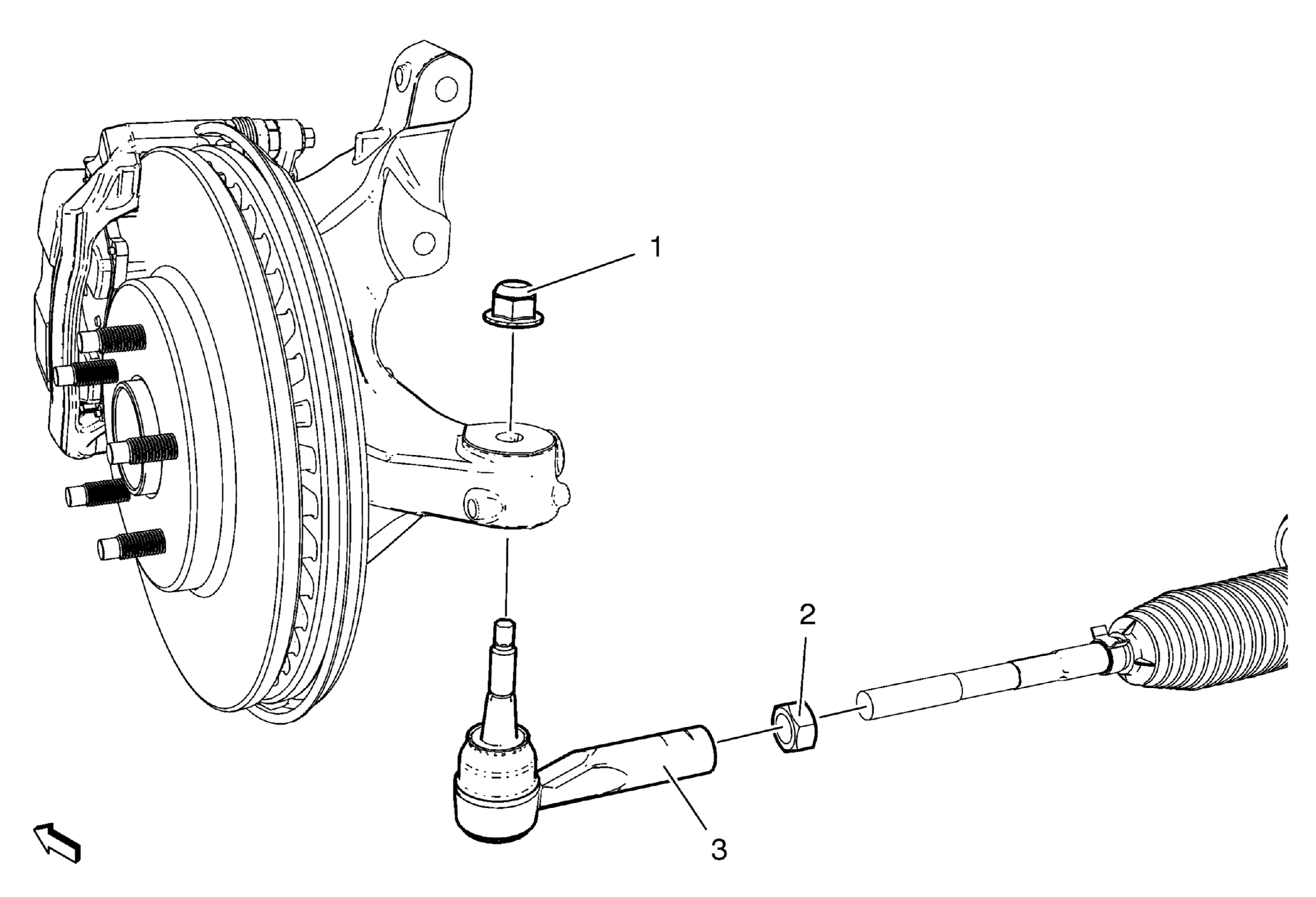 Courtesy of GENERAL MOTORS COMPANY
 Steering Linkage Outer Tie Rod Replacement
| Callout |
Component Name |
|
Preliminary Procedures
- Raise and support the vehicle. Refer to Lifting and Jacking the Vehicle
.
- Remove the front tire and wheel assembly. Refer to Tire and Wheel Removal and Installation
.
|
| 1 |
Steering Linkage Outer Tie Rod Nut
Procedure
Install steering linkage outer tie rod nut.
Tighten
- Tighten the nut a first pass to 35 Nm (26 lb ft)
- Tighten the nut a second pass 30 to 40 degrees
Special Tools
EN-45059
Angle Meter
For equivalent regional tools, refer to Special Tools .
|
| 2 |
Steering Linkage Inner Tie Rod Nut Procedure
- Use paint in order to place match marks on the steering linkage inner tie rod nut and on the steering linkage inner tie rod.
- During the installation, align the match marks.
- Do not tighten the nut during the installation. Tighten the nut after adjusting the front toe. Refer to Wheel Alignment - Steering Wheel Angle and/or Front Toe Adjustment
.
|
| 3 |
Steering Linkage Outer Tie Rod
CAUTION:
Do not free the ball stud by using a pickle fork or a wedge-type tool. Damage to the seal or bushing may result.
Procedure
- Use the CH-24319-B
puller in order to separate the steering linkage outer tie rod from the steering knuckle.
- Inspect the steering linkage inner tie rod for bent or damaged threads.
- Clean the tapered surface of the steering knuckle.
- After the installation, measure and adjust the front toe. Refer to Wheel Alignment - Steering Wheel Angle and/or Front Toe Adjustment
.
- Center the steering angle sensor. Refer to Steering Angle Sensor Centering
.
Special Tools
CH-24319-B
Steering Linkage and Tie Rod Puller
For equivalent regional tools, refer to Special Tools . |