DTC B1971: Inadvertent Power Fault: Testing
- Perform lighting system diagnostic system check. See LIGHTING SYSTEM DIAGNOSTIC SYSTEM CHECK
under SELF-DIAGNOSTIC SYSTEM. After performing diagnostic system check, go to next step.
- Turn ignition off. Connect scan tool to DLC. Turn ignition on. Select DELAY INTERIOR LIGHTS from light test menu in SPECIAL FUNCTIONS. Command DIL relay on and off by pressing on and off buttons on scan tool. If status changes with commanded state, go to DIAGNOSTIC AIDS
. If status does not change with commanded state, go to next step.
- Check DOME LAMP fuse (10-amp) in fuse block. If DOME LAMP fuse is open, go to step 9
. If DOME LAMP fuse is not open, go to next step.
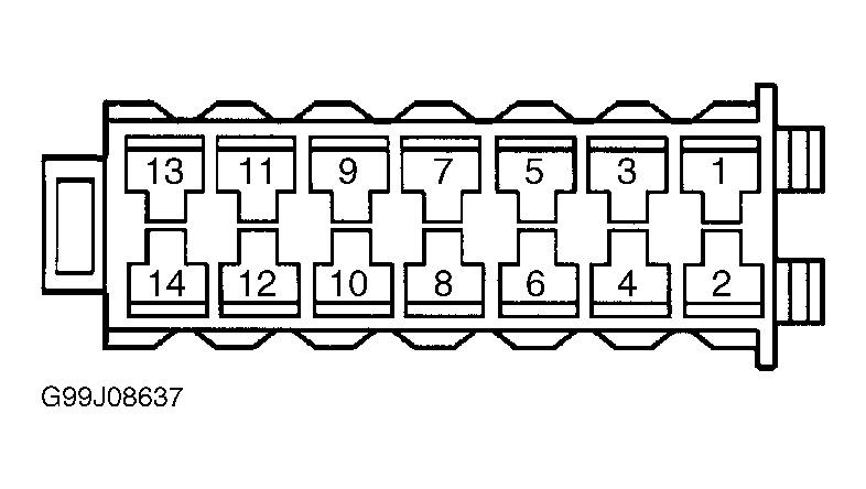
- Turn ignition off. Disconnect multifunction relay module harness connector. See Figure
. Turn ignition on. Using a test light connected to good ground, probe multifunction relay module terminal No. 5 (Red wire). See Fig 1
. If test light illuminates, go to next step. If test light does not illuminate, go to step 10
.
- Turn ignition on. Using a test light connected between multifunction relay module terminals No. 5 (Red wire) and No. 7 (Brown/Purple wire), press on and off buttons on scan tool to change state of DIL relay from on to off. See Fig 1
. If test light illuminates with each scan tool command, go to step 13
. If test light does not illuminate with each scan tool command, go to next step.
- If test light remains illuminated with each scan tool command in step 5
, go to step 11
. If test light does not remain illuminated with each scan tool command in step 5
, go to next step.
- Disconnect BCM 32-pin connector C2. See Figure
. Using DVOM, check for an open or high resistance in Brown/Purple wire between multifunction relay module harness connector terminal No. 7 and BCM connector C2 terminal C3. See Figure
and Fig 1
. If fault is located and repaired, go to step 15
. If fault is not located and repaired, go to next step.
- Using DVOM, check for a short to battery voltage in Brown/Purple wire between multifunction relay module harness connector terminal No. 7 and BCM connector C2 terminal C3. If fault is located and repaired, go to step 15
. If fault is not located and repaired, go to step 14
.
- Using DVOM, check for a short to battery voltage in Red wire between multifunction relay module harness connector terminal No. 5 and fuse block. If fault is located and repaired, go to step 15
. If fault is not located and repaired, go to step 12
.
- Using DVOM, check for an open or high resistance in Red wire between multifunction relay module harness connector terminal No. 5 and fuse block. After fault is located and repaired, go to step 15
.
- Using DVOM, check for a short to ground in Brown/Purple wire between multifunction relay module harness connector terminal No. 7 and BCM connector C2 terminal C3. After fault is located and repaired, go to step 15
.
- Using DVOM, check for a short to ground in Red/Blue wire between multifunction relay module harness connector terminal No. 2 and all courtesy lights. See WIRING DIAGRAMS
. After fault is located and repaired, go to step 15
.
- Replace multifunction relay module. See Figure
. After replacement, go to step 15
.
- Replace BCM. See BODY CONTROL MODULE (BCM)
under REMOVAL & INSTALLATION. Reprogram BCM. See PROGRAMMING
. After replacement, go to next step.
- Use scan tool to clear DTCs. Recheck system operation by performing step 2
. If BCM operates properly and DTC B1971 is not set, system is okay.
 Courtesy of GENERAL MOTORS CORP.