Drive Motor Battery Charger Replacement
 Courtesy of GENERAL MOTORS COMPANY
 Drive Motor Battery Charger Replacement
| Callout |
Component Name |
WARNING:
Always perform the High Voltage Disabling procedure prior to servicing any High Voltage component or connection. Personal Protection Equipment (PPE) and proper procedures must be followed.
The High Voltage Disabling procedure includes the following steps:
- Identify how to disable high voltage.
- Identify how to test for the presence of high voltage.
- Identify condition under which high voltage is always present and personal protection equipment (PPE) and proper procedures must be followed.
Before working on any high voltage system, be sure to wear the following Personal Protection Equipment:
- Safety glasses with appropriate side shields when within 15 meters (50 feet) of the vehicle, either indoors or outdoors.
- Certified and up-to-date Class "0" Insulation gloves rated at 1000V with leather protectors.
- Visually and functionally inspect the gloves before use.
- Wear the Insulation gloves with leather protectors at all times when working with the high voltage battery assembly, whether the system is energized or not.
Failure to follow the procedures may result in serious injury or death.
Preliminary Procedures
- Disable the high voltage system. Refer to High Voltage Disabling
.
- Remove the front bumper fascia. Refer to Front Bumper Fascia Removal and Installation
.
- Disconnect the electrical connectors.
NOTE:
Add a protective bag or enclosure to the harness side connector to prevent inadvertent liquid spills during rework. Corrosion will form if this procedure is not followed properly.
- Disconnect the coolant hoses from the charger assembly. Refer to Generator Control Module Coolant Radiator Hose Replacement
, and Drive Motor Battery Coolant Cooler Outlet Hose Replacement (Battery Outlet to Valve)
.
|
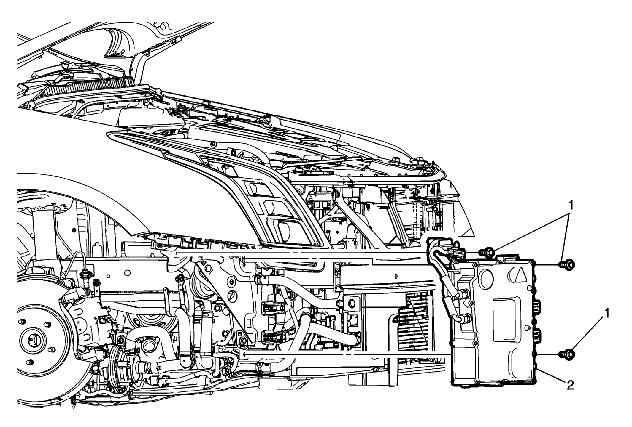
| 1 |
Drive Motor Battery Charger Fastener (Qty: 3)
Tighten
22 (16 lb ft) |
| 2 |
Drive Motor Battery Charger Assembly Procedure
- Connect the electrical connectors
- Connect the coolant hoses to the charger assembly.
- Fill the drive motor battery charger cooling system. Refer to Drive Motor Generator Power Inverter Module Cooling System Draining and Filling
.
- Enable the high voltage system. Refer to High Voltage Enabling
.
- Program the drive motor battery charger. Refer to Battery Charger Programming and Setup
.
|