Test B: Keyless Entry System Inoperative
- If description and operation has been reviewed, go to next step. If description and operation has not been reviewed, review description and operation. See DESCRIPTION & OPERATION
.
- Using remote transmitter, lock and unlock doors. If doors do not lock and unlock properly, go to next step. If doors lock and unlock properly, diagnose intermittent problem. See appropriate BODY CONTROL MODULES article.
- Reprogram Remote Control Door Lock Receiver (RCDLR), see TRANSMITTER PROGRAMMING
under PROGRAMMING. If system does not operate properly, go to next step. If system operates properly after programming, go to step 12
.
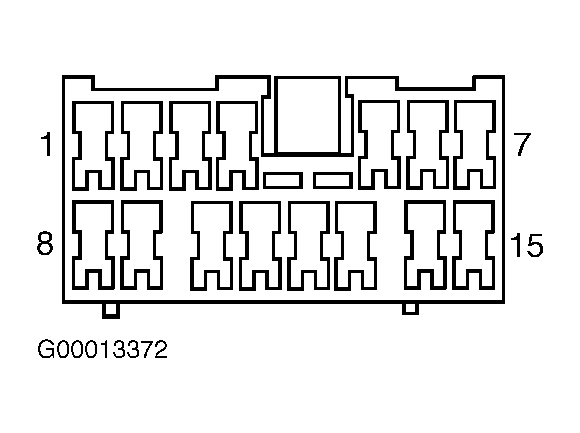
- Disconnect RCDLR 15-pin harness connector. RCDLR is located under left side of instrument panel above junction block No. 1. Measure voltage between ground and RCDLR harness connector terminal No. 8 (Blue/Yellow wire). See Fig 1
. If battery voltage exists, go to next step. If battery voltage does not exist, repair open or short to ground in Blue/Yellow wire between RCDLR and fuse and relay box No. 1. After repair go to step 12
.
- Turn ignition switch to RUN position. Measure voltage between ground and RCDLR harness connector terminal No. 13 (Red/Blue wire). See Fig 1
. If battery voltage exists, go to next step. If battery voltage does not exist, go to step 10
.
- Measure resistance between ground and RCDLR harness connector terminal No. 1 (White/Black wire). See Fig 1
. If resistance is less than 2 ohms, go to next step. If resistance is 2 ohms or more, repair open in White/Black wire between RCDLR and junction block No. 1. After repair, go to step 12
.
- Turn ignition switch to LOCK position and remove ignition key. Measure resistance between ground and RCDLR harness connector terminal No. 10 (Blue/Black wire). See Fig 1
. If resistance is 2 ohms or more, go to next step. If resistance is less than 2 ohms, repair short to ground in Blue/Black wire between RCDLR and junction block No. 1. After repair, go to step 12
.
- Measure resistance in Red/White wire between RCDLR harness connector terminal No. 14 and splice SP261. See WIRING DIAGRAMS
. If resistance is less than 2 ohms, go to next step. If resistance is 2 ohms or more, repair open or high resistance in Red/White wire between RCDLR and splice SP261. After repair, go to step 12
.
- Inspect RCDLR harness connector for loose or corroded terminals. Check for intermittent condition. See appropriate BODY CONTROL MODULES article. If problem still exists, go to step 11
. If problem does not exist, go to step 12
.
- Repair open in Red/Blue wire between RCDLR and junction block No. 2. See WIRING DIAGRAMS
. After repair, go to step 12
.
- Replace RCDLR. Program remote transmitters, see TRANSMITTER PROGRAMMING
under PROGRAMMING. After repair, go to next step.
- Operate system to verify repair. If problem does not exist, system is okay. If problem still exists, go to step 3
.
 Courtesy of GENERAL MOTORS CORP.