Diagnostic Procedure
- Perform Diagnostic System Check - Engine Controls. See DIAGNOSTIC SYSTEM CHECK - ENGINE CONTROLS
under SELF-DIAGNOSTIC SYSTEM in SELF-DIAGNOSTICS - 2.5L TRACKER article. After performing Diagnostic System Check - Engine Controls, go to next step.
- If DTC P0505, P0506 or P0507 is present or pending, see DTC P0505: IDLE CONTROL SYSTEM
, DTC P0506: IDLE SPEED - LOW
or DTC P0507: IDLE SPEED - HIGH
under DIAGNOSTIC TESTS in SELF-DIAGNOSTICS - 2.5L TRACKER article. If DTC P0505, P0506 or P0507 is not present or pending, go to next step.
- Start engine and warm to normal operating temperature. Using scan tool, observe Engine Speed and IAC Motor Command parameters. If IAC Motor Command parameter is 10-50 percent with Engine Speed parameter at 700-800 RPM (Park or Neutral), go to step 5. If IAC Motor Command parameter is not 10-50 percent with Engine Speed parameter at 700-800 RPM (Park or Neutral), go to next step.
- Start engine and warm to normal operating temperature. Select RPM control, under IAC system, in Special Functions menu of scan tool. Command IAC valve to increase and decrease engine speed. If engine speed increases and decreases as commanded, go to next step. If engine speed does not increase or decrease as commanded, go to step 8
- Start engine. Place transmission in Park or Neutral. Operate headlights, HVAC blower motor (AC off) and rear window defogger (if equipped) one at a time, while observing Engine Speed and IAC Motor Command parameters on scan tool. If Engine Speed parameter stays within 700-800 RPM and IAC Motor Command parameter increases 2-3 percent, go to next step. If Engine Speed and IAC Motor Command parameters are not as specified, see ELECTRICAL/ACCESSORY LOAD IDLE-UP CIRCUIT DIAGNOSIS .
- Turn HVAC blower motor and AC on (if equipped). If Engine Speed parameter is 750-850 RPM and IAC Motor Command parameter increases 4-12 percent, go to next step. If Engine Speed and IAC Motor Command parameter are not as specified, see ELECTRICAL/ACCESSORY LOAD IDLE-UP CIRCUIT DIAGNOSIS .
- Turn all accessories off. Ensure engine is at normal operating temperature. Using scan tool, observe Engine Speed and IAC Motor Command parameters. If Engine Speed parameter is 700-800 RPM (Park and Neutral) and IAC Motor Command parameter is 10-50 percent, system is okay. If engine RPM and IAC duty cycle are not as specified, go to ROUGH, UNSTABLE OR INCORRECT IDLE & STALLING
symptom under SYMPTOMS (GASOLINE) in TROUBLE SHOOTING - NO CODES article.
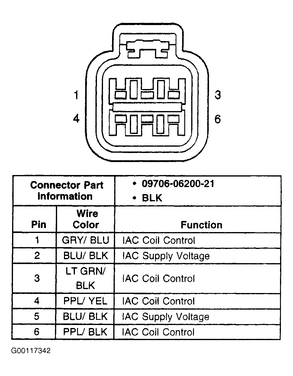
- Turn ignition off and disconnect IAC valve connector. Using DVOM, measure resistance between the following IAC valve terminals: No. 1 and 2, No. 2 and 3, No. 4 and 5, and No. 5 and 6. See Fig 1. If resistance is 21-23 ohms at 68°F (20°C), go to next step. If resistance is not 21-23 ohms, go to step 15.
- Turn ignition on, engine off. Using test light connected to ground, probe IAC valve harness connector terminals No. 2 and 5 (Blue/Black wires). If test light illuminates on both circuits, go to next step. If test light does not illuminate on both circuits, go to step 12.
- Turn ignition off. Reconnect IAC valve connector. Disconnect PCM 28-pin harness connector C4. Turn ignition on, engine off. Using DVOM, measure voltage between ground and PCM harness connector C4 terminals No. 14 (Purple/Black wire), No. 15 (Light Green/Black wire), No. 24 (Purple/Yellow wire) and No. 25 (Gray/Blue wire). If battery voltage exists at all terminals, go to next step. If battery voltage does not exist at all terminals, go to step 13.
- Turn ignition off. Reconnect PCM connector C4. Start engine and warm to normal operating temperature. Using DVOM connected to ground, backprobe IAC coil control circuits at PCM harness connector C4 terminals No. 14 (Purple/Black wire), No. 15 (Light Green/Black wire), No. 24 (Purple/Yellow wire) and No. 25 (Gray/Blue wire). Observe voltage display on DVOM for each IAC Coil Control circuit while increasing and decreasing engine speed with scan tool RPM Control function. If voltage of each circuit changes from high to low with increase and decrease in engine speed, go to step 14. If voltage of each circuit does not change from high to low with increase and decrease in engine speed, go to step 16.
- Repair high resistance or open in Ignition Positive Voltage circuit. After repairs, go to step 17.
- Repair open, short to ground or high resistance in any IAC coil control circuit that did not measure battery voltage in step 10)
. After repairs, go to step 17.
- Remove IAC valve. Inspect idle air passage for restrictions or blockage. Repair as necessary. After repairs, go to step 17. If idle air passages are not restricted, go to next step.
- Replace IAC valve. After repairs, go to step 17.
- Replace PCM. Perform PCM relearn procedures. See PROGRAMMING
in SELF-DIAGNOSTICS - 2.5L TRACKER
article. After repairs, go to next step.
- Operate vehicle within conditions under which original symptom was observed. Using scan tool, retrieve DTCs. If no DTCs are set, system is okay. If no DTCs are set, and concern is still present, go to DIAGNOSTIC AIDS . If any DTCs are set, perform appropriate DTC test. See DIAGNOSTIC TROUBLE CODE DEFINITIONS
in SELF-DIAGNOSTICS - 2.5L TRACKER article.
 Courtesy of GENERAL MOTORS CORP.