Without Special Tool
ELECTRONIC IGNITION (EI) SYSTEM DIAGNOSIS (WITHOUT SPECIAL TOOL)
CIRCUIT DESCRIPTION
Each ignition coil supplies secondary voltage to a pair of spark plugs. This is called a waste spark ignition system. The engine control module (ECM) supplies a signal on each of the ignition control (IC) timing circuits to the ignition control module (ICM). The ICM fires the correct ignition coil at the correct time based on the signals. The ICM detects if cylinder 1 or cylinder 3 is on the compression stroke by sensing the secondary voltage and polarity of each side of the ignition coil. The ICM detects this voltage with sensing circuitry integrated into each ignition coil. The higher voltage is on the compressing cylinder. This is called compression sense ignition. The ICM provides a synthesized cam signal to the ECM based on these inputs. The ECM uses the cam signal to synchronize fuel injection.
This system consists of the following circuits:
- An ignition voltage circuit
- A ground circuit
- A camshaft position (CMP) sensor signal circuit
- An IC timing control circuit for cylinders #1 and #4
- An IC timing control B circuit for cylinders #2 and #3
TEST
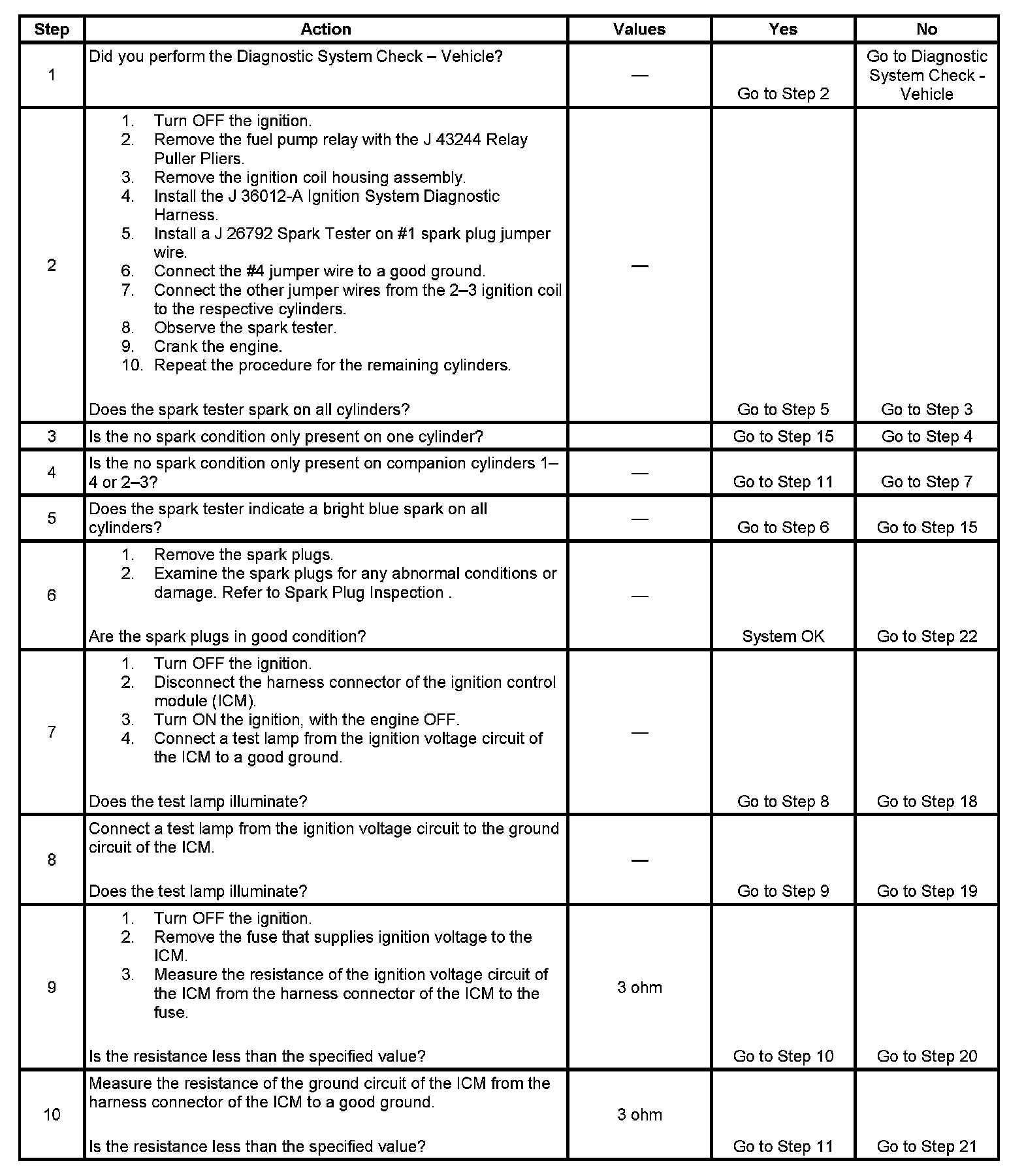
Step 1 - Step 10:
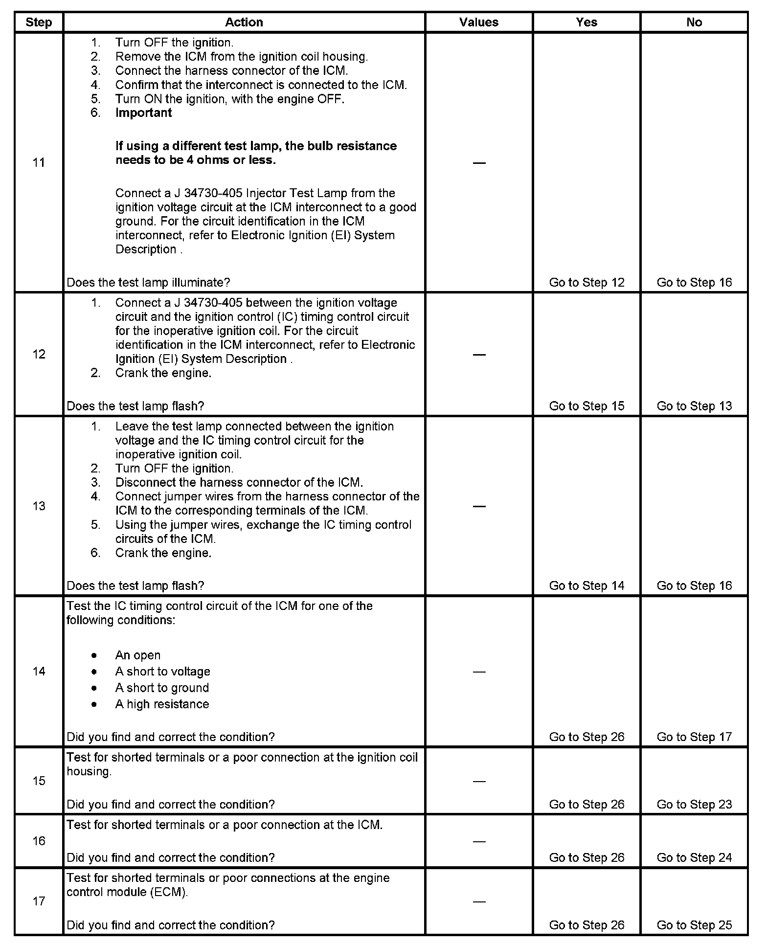
Step 11 - Step 17:
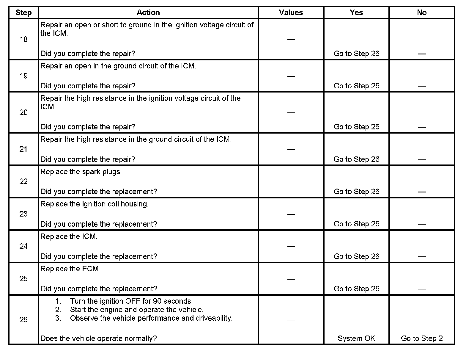
Step 18 - Step 26: