DTC P0703: Brake Switch Sense Circuit: Testing
- Turn ignition off. Disconnect brakelight switch connector. Measure resistance between ground and Black/Light Green wire at brakelight switch harness connector. If resistance is less than 5 ohms, go to next step. If resistance is 5 ohms or more, repair open between Black/Light Green wire and ground. See WIRING DIAGRAMS article.
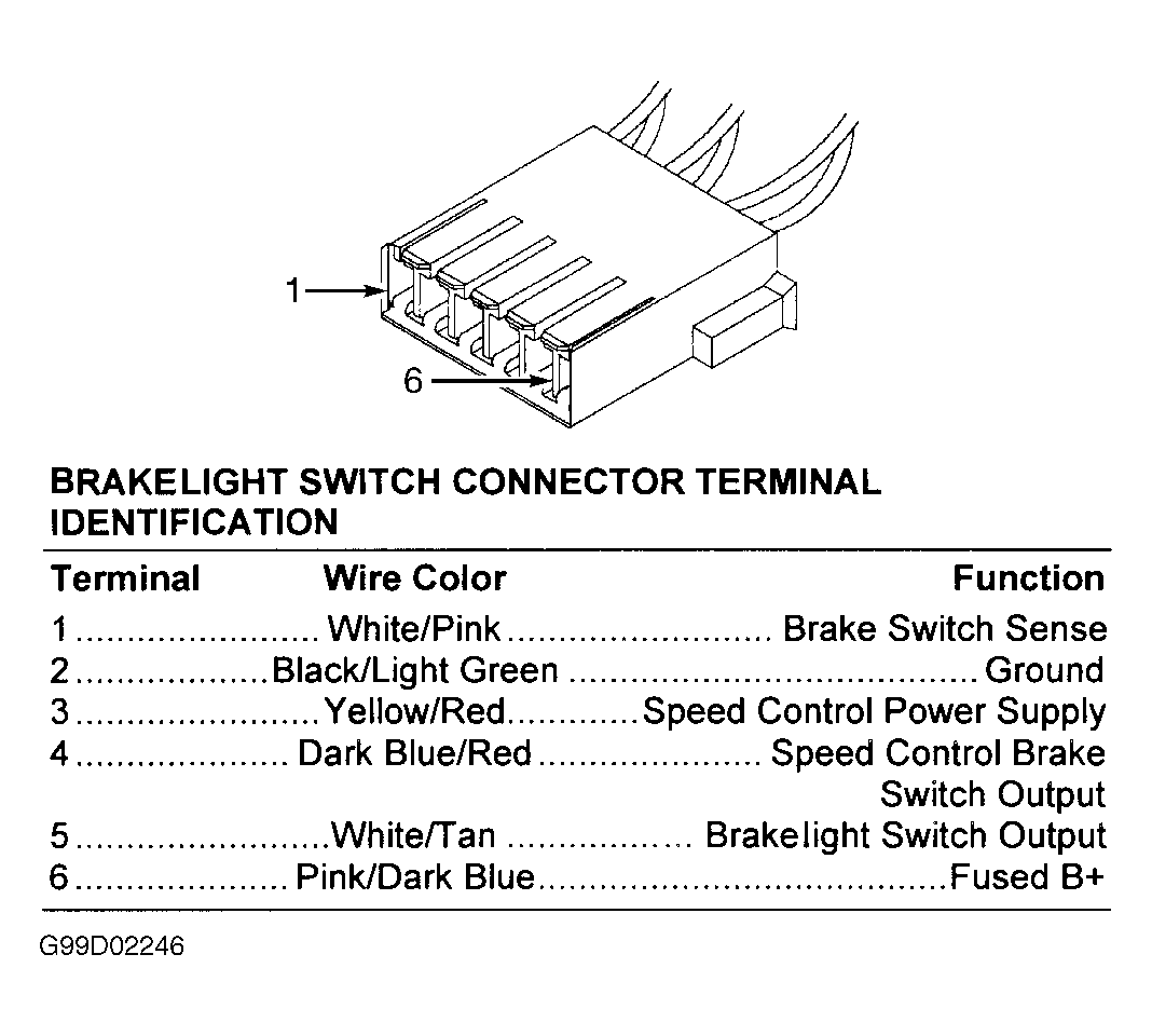
- Ensure ignition is off. Disconnect PCM connectors. PCM is located on left side of engine compartment, between Power Distribution Center (PDC) and Transmission Control Module (TCM). See Figure. Inspect connectors for damaged pins, corrosion and loose terminals. Repair connectors as necessary. If connectors are okay, measure resistance of White/Pink wire between terminal No. 1 at brakelight switch harness connector and terminal No. 62 at PCM C2 harness connector. See Figure and Fig 1
. If resistance is less than 5 ohms, go to next step. If resistance is 5 ohms or more, repair open in White/Pink wire.
- Measure resistance between terminals No. 1 and 2 at brakelight switch (component side). See Fig 1. With brake pedal released, resistance should be less than 5 ohms. With brake pedal depressed, resistance should be 5 ohms or more. If resistance is as specified, go to next step. If resistance is not as specified, replace brakelight switch.
- Measure resistance between ground and terminal No. 1 (White/Pink wire) at brakelight switch harness connector. If resistance is 5 ohms or more, go to next step. If resistance is less than 5 ohms, repair short to ground in White/Pink wire.
- At this time, PCM is assumed to be defective. Replace PCM.
 Courtesy of DAIMLERCHRYSLER CORPORATION