- Install the steering column on the steering column support bracket. Loosely install the two steering column attaching nuts.
- Loosely tighten the two steering column upper mounting nuts (Figure
) to hold the steering column in place. Center the steering column in place, side to side, then install the two lower mounting bolts (Figure
). Then equally tighten both steering column upper mounting nuts until upper steering column mounting bracket is seated against support bracket. Tighten the four steering column bracket to support bracket fasteners to 12 N.m (105 in. lbs.), tightening the upper mounting nuts first, then the lower mounting bolts.
- Assemble the intermediate steering shaft to the steering column flex coupler (Figure
). Tighten the coupler pinch bolt nut to a torque of 27 N.m (240 in. lbs.). Be sure to install steering coupler pinch bolt retaining pin.
- Install the two air ducts under the steering column (Figure
).
- If the vehicle is equipped with a floor shifter, install the shifter/ignition interlock cable (Figure
) in the lock cylinder housing.
- Install the shift cable mounting bracket (Figure
) on the steering column. The shift cable mounting bracket is mounted to the steering column by the two mounting screws.
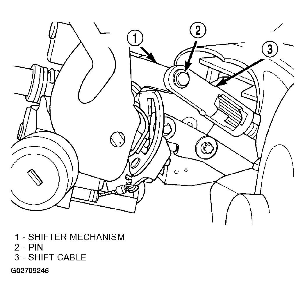
- If the vehicle is equipped with a steering column mounted shift lever, first verify that the shift lever is locked in the park position. Then, install the shift cable on the shifter mechanism (Fig 1
). The shift cable must be fully inserted onto the pin of the shifter mechanism.
 Courtesy of DAIMLERCHRYSLER CORP.
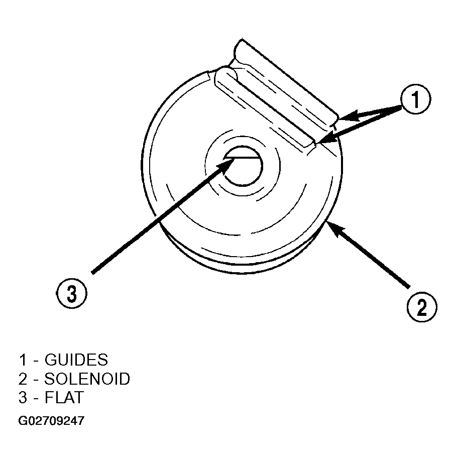
- If the vehicle is equipped with a steering column mounted shift lever, install the brake transmission interlock solenoid on the shift lever mechanism. To do so, perform the following:
- Align the flat inside the solenoid (Fig 2
) with the flat on the shift lever mounting stud.
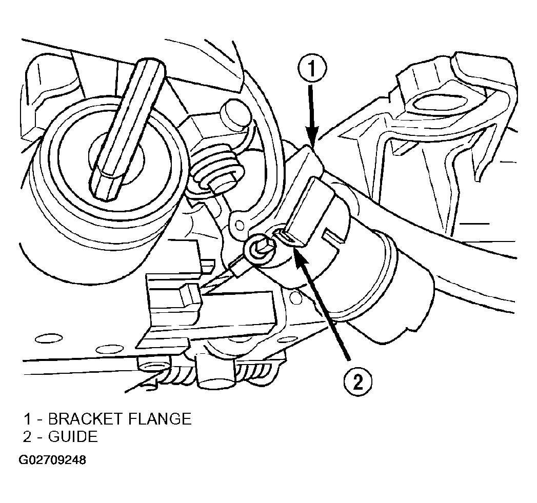
- Slide the solenoid completely onto the shift lever mounting stud aligning the plastic guide formed into the solenoid housing with the flange on the shift lever mechanism bracket (Fig 3
).
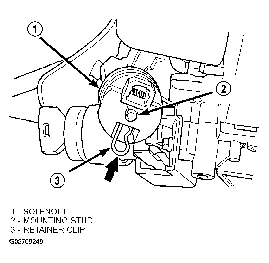
- Install the retainer clip until it snaps into place in the slot cut into the shift lever mounting stud (Fig 4
).
- Verify the solenoid is locked in place and will not slide off the mounting stud.
- Connect the wiring harness connector to the solenoid.
 Courtesy of DAIMLERCHRYSLER CORP.
 Courtesy of DAIMLERCHRYSLER CORP.
 Courtesy of DAIMLERCHRYSLER CORP.
- Install the ignition switch on the steering column. Install and securely tighten the 2 screws (Figure
) mounting the ignition switch to the steering column.
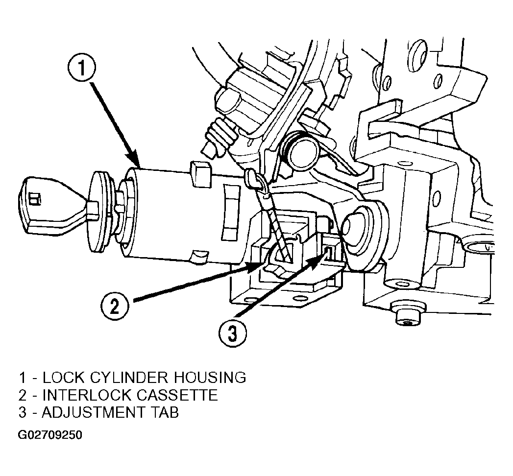
- If the vehicle is equipped with a steering column mounted shift lever and if a new ignition shift interlock cassette has been installed, the interlock system must be adjusted. Adjust the interlock system by pushing in on the adjustment tab until it stops (Fig 5
). The adjustment tab will click as it moves into position. Ensure the tab is fully depressed.
 Courtesy of DAIMLERCHRYSLER CORP.
- Install the multifunction switch on the steering column. Install and securely tighten the two screws (Figure
) mounting the multifunction switch to the steering column. Install the clockspring wiring harness on the routing clip on the top of the multifunction switch.
- If the vehicle is equipped, clip the SKIM module over the key cylinder halo bezel and attach it to the steering column with its mounting screw. Connect the wiring harness to the module.
- Install the clockspring on the steering column. Install and securely tighten the two screws (Figure
) mounting the clockspring to the steering column.
- Install the wiring harness connectors (Figure
) on the clockspring.
- If removed, install the trim ring for the key cylinder on the lock cylinder housing.
- Install the lower shroud (Figure
) on the steering column. Install and securely tighten the 2 screws attaching the lower shroud to the steering column.
- Install the tilt lever (Figure
) on the steering column.
- Install the upper shroud on the steering column by snapping it onto the lower shroud.
CAUTION:
If any doubt is present as to whether the clockspring is properly centered, This clockspring centering procedure MUST be performed prior to installing steering wheel assembly. If clockspring is not centered it may be overextended, causing clockspring assembly to become inoperative. The yellow centering indicator must be present in the centering window of the clockspring and the arrow on the clockspring must be pointing at the drive pin.
- Center the clock spring using the following procedure.
- Depress the plastic locking pin to disengage clockspring locking mechanism.
- Keeping locking mechanism disengaged, rotate the clockspring rotor in the CLOCKWISE DIRECTION to the end of the travel. Do not apply excessive torque.
- From the end of clockwise travel, slowly rotate the rotor in the counterclockwise direction until yellow appears in the centering window of clockspring. When yellow appears in the centering window the arrow on the clockspring will be pointing at the drive pin on clock spring rotor.
- Engage the clockspring locking mechanism.
CAUTION:
When installing the steering wheel, use care not to damage the steering wheel finish. The wood grain on some steering wheels can be easily marred.
CAUTION:
Do not install steering wheel by driving it onto the shaft. Pull steering wheel down onto steering column shaft using ONLY the steering wheel retaining nut.
- Feed the clockspring wiring leads through the steering wheel (Figure
). Install steering wheel on shaft of steering column, making sure the master serration in the wheel hub and on the steering column shaft line up.
- Install steering wheel to steering column shaft retaining nut (Figure
) and tighten until the steering wheel is fully installed on the shaft. Tighten steering wheel retaining nut to a torque of 61 N.m (45 ft. lbs.).
- Turn the key cylinder to the unlock position, unlocking the steering column shaft.
- Connect the horn switch wiring lead from the clockspring to the driver airbag horn switch wiring lead (Figure
).
- Install the airbag electrical lead into connector on back of driver airbag (Figure
). Be sure electrical connector from clockspring is securely latched into driver airbag connector.
- If optional audio control switches are present on the rear of the steering wheel, connect the 4-way connector lead from the clockspring to the steering wheel wiring harness lead. Once connected, place the connector in back cover formation located at the 12 O'clock position.
CAUTION:
The fasteners, screws, and bolts, originally used for the airbag components are specifically designed for the airbag system. They must never be replaced with any substitutes. Anytime a new fastener is needed, replace only with correct fasteners provided in service packages or fasteners listed in the parts book.
NOTE:
Make sure steering wheel and airbag module are in the right-side-up position before installing airbag module on steering wheel.
- Install the airbag module on steering wheel. Install only the two original or correct replacement airbag module attaching bolts (Figure
). Tighten the two airbag module attaching bolts to a torque of 8 N.m (75 in. lbs.).
- Connect the speed control wiring leads to the speed control switches.
- Install the speed control switches in the steering wheel (Figure
). Install the screws attaching the speed control switches to the steering wheel. Tighten the screws to a torque of 1.5 N.m (13 in. lbs.).
- Install the diagnostic connector on the reinforcement (Figure
).
- Install the reinforcement on the instrument panel (Figure
). Install the four bolts mounting the reinforcement to the instrument panel.
- Install the parking brake release cable on the parking brake release handle in the lower instrument panel cover (Figure
).
- Install the wiring harness connector on the trunk release switch in the lower instrument panel cover (Figure
).
- Install the lower instrument panel cover.
- Install the two screws behind the fuse panel cover attaching the lower instrument panel cover to the instrument panel (Figure
).
- Install the fuse panel cover on the left end of the instrument panel (Figure
).
CAUTION:
When reconnecting the battery terminals on a vehicle that has had the airbag module removed, ensure that no occupants are in the vehicle, then perform the following procedure.
- Using the following procedure, reconnect the remote ground cable on the shock tower ground stud.
- Connect DRBIII(R) scan tool to diagnostic connector below the column.
- Turn ignition key to ON position. Exit vehicle with the DRBIII(R) scan tool.
- Ensuring that there are no occupants in the vehicle, connect negative cable to negative post of the battery.
- Using the DRBIII(R) scan tool, read and record active fault codes. Also read and record any stored fault codes. Refer to BODY DIAGNOSTIC PROCEDURES
if any faults are found.
- Erase stored faults if there are no active fault codes. If problems remain, fault codes will not erase.
- From the passenger side of the vehicle, turn ignition key to OFF and then ON observing instrument cluster airbag lamp. It should go on for six to eight seconds, then go out. This will indicate that the airbag system is functioning normally.
- If airbag warning lamp fails to light, blinks on and off or goes on and stays on, there is an airbag system malfunction. Refer to BODY DIAGNOSTIC PROCEDURES
to diagnose the system malfunction.
- Test the operation of the horn, lights and any other functions that are steering column operated. If applicable, reset the radio and the clock.
- Road test vehicle to ensure proper operation of the steering system and the speed control system.