System Function
- Disconnect SPOUT jumper. See appropriate EEC-IV article in COMPUTERIZED ENGINE CONTROL section listed below. If spark angle is 7-13 degrees BTDC, go to step 2). If not, go to step 3).
- With SPOUT jumper connected during Self-Test. Is spark angle 27-33 degrees BTDC. If not, replace DIS module. If so, go to step 4).
- Inspect vane cups on back of crankshaft damper. Replace any bent or damaged cups. If vane cups are okay, replace crank sensor.
- Crank engine. If cranking is smooth and regular (does not backfire or pause), go to step 7). If cranking is not smooth and regular, go to step 5)
- Using Neon Spark Tester (Champion CT-436), crank engine while watching for continuous spark at all plug wires. If a contin- uous spark is present at all plug wires, go to step 6). If not, go to step 8).
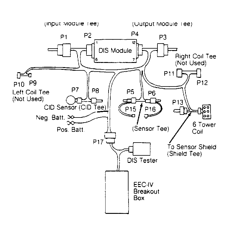
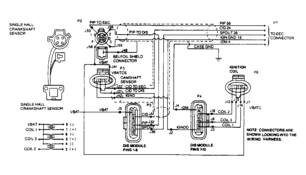
- Install DIS Diagnostic Cable (Hickok HK-100-306) and EEC breakout box. See Fig 1. While cranking engine in very short bursts, measure voltage between J51 and J2. See Fig 2. If 2 readings of zero and 10-12 volts are observed during cranking (5.4-7.4 volts if engine runs), replace DIS module. If the 2 readings are not present, go to DIS MODULE, HARNESS & SENSORS test in this article step 1).
- Using neon spark tester, check for spark at all plug wires. If there is continuous spark at all plug wires, go to step 11). If there is not continuous spark at all plug wires, go to step 8).
- Using Air Gap Spark Tester (D81P-6666-A) at coil, ensure their is good Blue spark at all coil towers. If there is good spark, go to DIS MODULE, HARNESS & COIL test, step 1) in this article. If not, go to step 9).
- If resistance of plug wires is less than 30k ohms, go to step 10). If plug wire resistance is more than 30k ohms, replace bad wires.
- Inspect spark plugs. If spark plugs are okay, go to DIS MODULE, HARNESS & COIL test, step 1). If spark plugs are not okay, replace damaged plugs.
- If resistance of plug wires is less than 30k ohms, go to step 12). If resistance of plug wires is more than 30k ohms, replace damaged wires.
- Inspect spark plugs. If spark plugs are okay, ignition system is okay. If spark plugs are not okay, replace damaged plugs.
- Install DIS diagnostic cable and EEC breakout box. While cranking the engine in very short bursts, measure voltage between J22 and negative battery terminal. If 2 readings, zero and 10-12 volts are present (5.5-7.5 volts if engine runs), CID sensor is okay. Go to TUNE-UP TROUBLESHOOTING in TUNE-UP section, and/or FUEL SYSTEMS TROUBLESHOOTING in FUEL SYSTEMS section. If the 2 readings are not present, go to step 14).
- With ignition off, if resistance between J42 and negative battery terminal is less than 5 ohms, go to appropriate EEC-IV article in COMPUTERIZED ENGINE CONTROLS section listed below. If more than 5 ohms, IGND circuit is damaged. Repair circuit.
- With ignition on, if voltage between J41 and J55 is more than 11 volts, replace Cylinder Identification (CID) sensor. If volt- age is less than 11 volts, go to step 16).
- Remove CID sensor from tee and repeat voltage check between J41 and J55. If 11 volts is present, replace CID sensor. If 11 volts is not present, VBATCS circuit has a fault. Repair harness.
- Install DIS diagnostic cable and EEC breakout box. While cranking engine in very short bursts, measure voltage between J33 and negative terminal of battery. If 2 readings, zero and 10-12 volts (5.5-7.5 volts if engine runs) are present, PIP sensor is okay, go to TUNE-UP TROUBLESHOOTING in TUNE-UP section and/or FUEL SYSTEMS TROUBLESHOOTING in FUEL SYSTEMS section. If the voltage readings are not present, go to step 18).
- If resistance between J55 and negative terminal of battery is less than 5 ohms, go to step 19). If resistance is more than 5 ohms, IGN GND circuit has a fault. Repair IGN GND circuit.
- With ignition on, if voltage between J56 and J55 is more than 11 volts, replace PIP sensor. If less than 11 volts, go to step 20).
- Remove PIP sensor from crank sensor tee. With ignition on, if voltage between J56 and J55 is more than 11 volts, replace PIP sensor. If 11 volts is not present, VBAT circuit has a fault. Repair harness.
 Courtesy of FORD MOTOR CO.
 Courtesy of FORD MOTOR CO.
 Courtesy of FORD MOTOR CO.
 Courtesy of FORD MOTOR CO.