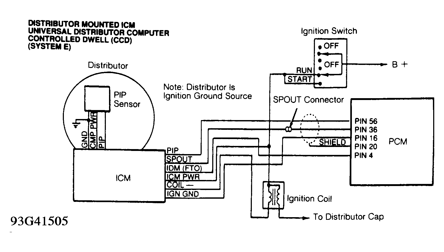
No Spark From Coil Secondary (Distributor Mounted ICM)
- Ensure that SPARK OUTPUT CHECK has been performed. See IGNITION CHECKS in BASIC TESTING
article in the ENGINE PERFORMANCE Section article. Turn ignition off. Connect EEC-IV Diagnostic Cable (007-00097) to EEC-IV Breakout Box (T83L-50-EECIV), negative battery terminal and ICM. See Fig 1. Ensure PIP OPEN/NORMAL/SPOUT OPEN switch is in NORMAL position. Apply DI overlay on breakout box. DO NOT connect EEC-IV Diagnostic Cable and PCM to EEC-IV Breakout Box simultaneously.
- Turn ignition on. Put DVOM on DC voltage scale. Measure voltage between J5 (TFI PWR) and J7 (B -). If voltage is less than 10 volts DC, repair open in TFI PWR circuit to ICM. If voltage is greater than 10 volts DC, put DVOM on AC voltage scale.
- Measure voltage between J7 (B -) and J15 (PIP) while cranking engine. If voltage is not 3.0-8.5 volts AC, go to step 5). If voltage is 3.0-8.5 volts AC, measure voltage between J7 (B -) and J10 (SPOUT) while cranking engine. If voltage is not 3.0-8.5 volts AC, go to step 9). If voltage is 3.0-8.5 volts AC, turn ignition off. Connect diagnostic cable to ignition coil wiring harness. Leave ignition coil disconnected.
- Set DVOM on DC voltage scale. Turn ignition on. Measure voltage between J2 (COIL PWR) and J7 (B -). If voltage is not greater than 10 volts DC, repair open circuit in ignition coil circuit. If voltage is greater than 10 volts DC, turn ignition off. Connect B + lead of diagnostic cable to positive battery terminal. Connect test light to J1 (B +) and J3 (COIL-). Crank engine. If test light does not flash brightly, go to step 16). If test light flashes brightly, replace coil, and perform QUICK TEST. See G - EEC-IV TESTS W/CODES article in the ENGINE PERFORMANCE Section.
- If voltage is not 3.0-8.5 volts AC in step 3), turn diagnostic cable switch to PIP OPEN position. Measure voltage between J7 (B -) and J15 (PIP) while cranking engine. If voltage is not 3.0-8.5 volts AC, go to step 8). If voltage is 3.0-8.5 volts AC, turn ignition off.
- Turn diagnostic cable switch to NORMAL position. Put DVOM on DC voltage scale. Disconnect diagnostic cable from ICM. Leave diagnostic cable attached to ICM wiring harness. Turn ignition on. Measure voltage between J7 (B -) and J15 (PIP). If voltage is greater than 0.5 volt, repair short in PIP circuit between PCM and ICM.
- If voltage is less than 0.5 volt, turn ignition off. Measure resistance between J7 (B -) and J15 (PIP). If resistance is greater than 10,000 ohms, replace PCM. If resistance is 10,000 ohms or less, repair short in PIP circuit between PCM and ICM.
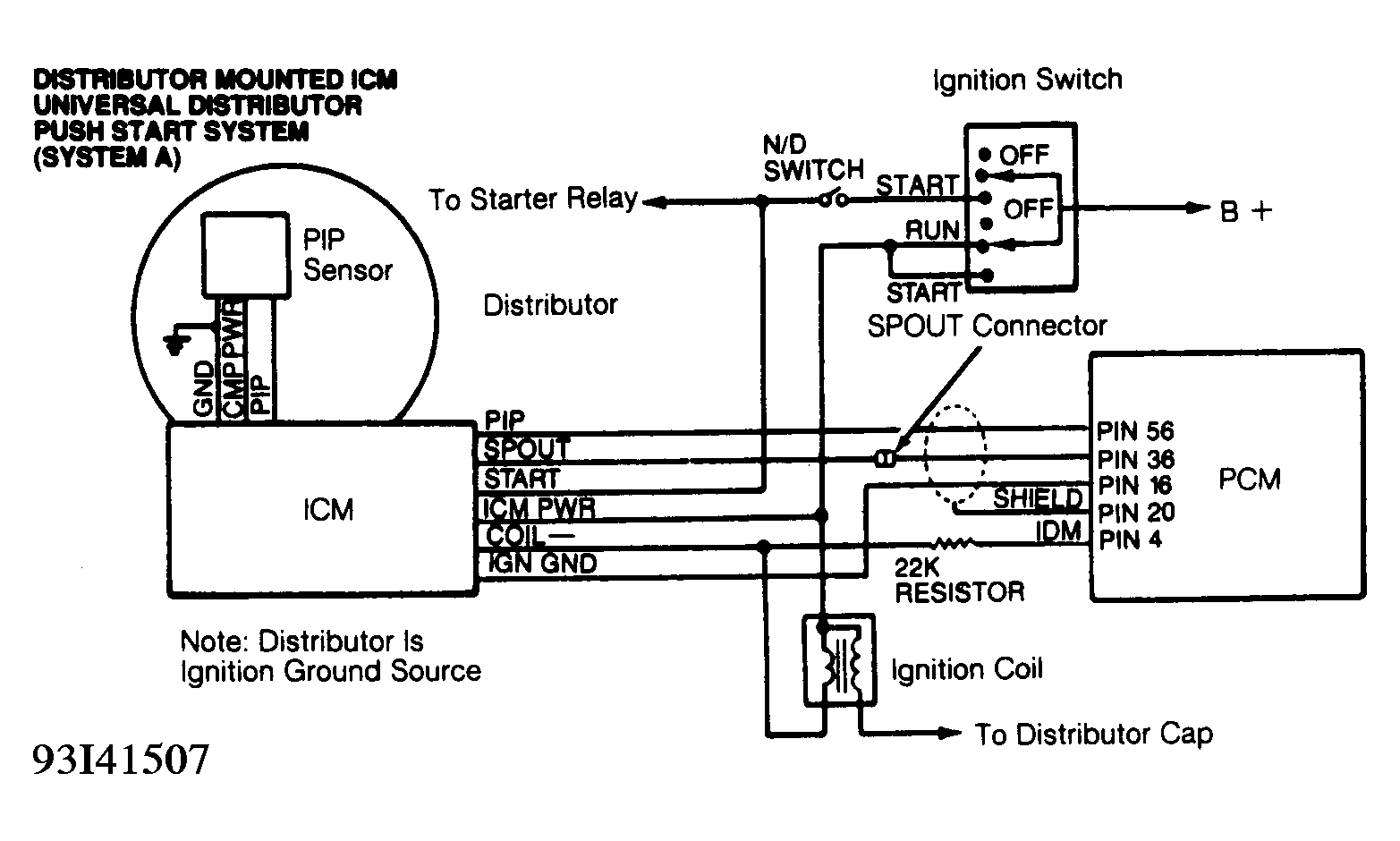
- If voltage is not 3.0-8.5 volts AC in step 5), turn ignition off. Remove ICM from distributor. Measure resistance of ICM circuits. See ICM RESISTANCE table. See Fig 2. If resistance is not as specified, replace ICM. If resistance is as specified, check stator and wiring inside distributor. Repair as necessary. If stator and wiring are okay, replace Camshaft Position (CMP) sensor.
ICM RESISTANCE
| Between Terminals |
Ohms |
| PIP (In) & PIP (Out) |
Less Than 150 |
| PIP PWR & TFI PWR |
Less Than 150 |
| GND & PIP (In) |
Greater Than 500 |
| GND & IGN GND |
Less Than 5 |
| PIP (In) & PIP PWR |
900-1500 |
- If voltage is not 3.0-8.5 volts AC in step 3), turn diagnostic cable switch to SPOUT OPEN position. Measure voltage between J7 (B -) and J10 (SPOUT) while cranking engine. If voltage is 3.0-8.5 volts AC, replace ICM.
- If voltage is not 3.0-8.5 volts AC, turn ignition off. Turn diagnostic cable switch to NORMAL position. Disconnect diagnostic cable from ICM. Leave diagnostic cable attached to ICM wiring harness. Turn ignition on. Measure voltage between J7 (B -) and J10 (SPOUT).
- If voltage is less than 0.5 volt DC, go to step 12). If voltage is greater than 0.5 volt DC, turn ignition off. Disconnect PCM. Turn ignition on. Measure voltage between J7 (B -) and J10 (SPOUT). If voltage is less than 0.5 volt DC, go to step 13). If voltage is greater than 0.5 volt DC, repair short to power in SPOUT circuit between PCM and ICM.
- Turn ignition off. Measure resistance between test pin J7 (B -) and J10 (SPOUT). If resistance is less than 10,000 ohms, disconnect PCM. Measure resistance between J7 (B -) and J10 (SPOUT). If resistance is still less than 10,000 ohms, repair short to ground in SPOUT circuit between PCM and ICM. If resistance is greater than 10,000 ohms, go to step 13).
- Measure resistance between breakout box test pin J15 (PIP) and PCM wiring harness connector terminal No. 56 (PIP). If resistance is greater than 5 ohms, repair open in PIP circuit between PCM and ICM. If resistance is less than 5 ohms, go to next step.
- Connect diagnostic cable to ICM. Measure resistance between breakout box test pin J7 (B -) and PCM wiring harness connector terminal No. 16 (IGN GND). If resistance is less than 5 ohms, replace PCM. If resistance is greater than 5 ohms, disconnect diagnostic cable from ICM.
- Measure resistance between breakout box test pin J9 (IGN GND) and PCM wiring harness connector terminal No. 16 (IGN GND). If resistance is less than 5 ohms, replace ICM. If resistance is greater than 5 ohms, repair open in IGN GND circuit between PCM and ICM.
- If test light does not flash brightly in step 4), disconnect diagnostic cable from ICM. Leave diagnostic cable attached to ICM wiring harness. Disconnect diagnostic cable from positive battery cable. Measure resistance between J3 (COIL-) and J4 (COIL-).
- If resistance is greater than 5 ohms, repair open in COIL- circuit between ignition coil and ICM. If resistance is less than 5 ohms, put DVOM on DC voltage scale. Turn ignition on. Measure voltage between J3 (COIL-) and J7 (B -). If voltage is greater than 5.5 volts DC, repair short to power in COIL- circuit between ignition coil and ICM. If voltage is less than 5.5 volts DC, go to next step.
- Turn ignition off. Measure resistance between J3 (COIL-) and J7 (B -). If resistance is less than 10,000 ohms, repair short in COIL- circuit between ignition coil and ICM. If resistance is greater than 10,000 ohms, replace ICM.