Pinpoint Test "A"
- Disconnect harness connector No. 1. See Fig 3
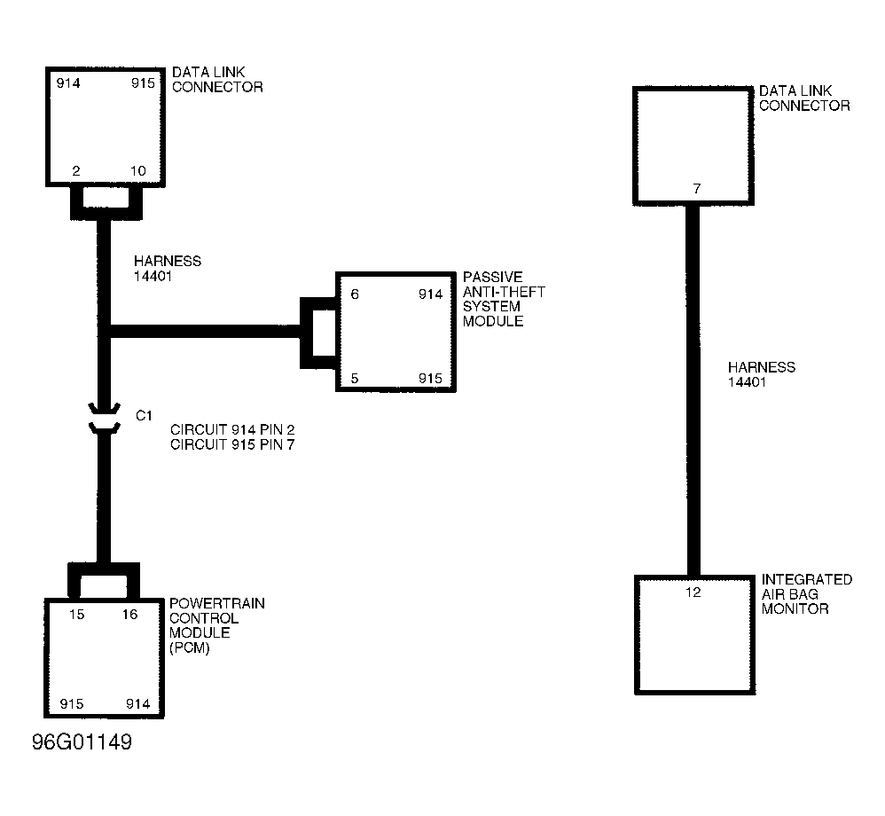
. Inspect connector and pin No. 2 (Tan/Orange wire) for damage or corrosion. If any faults are found, repair as necessary. If no faults are found, go to next step.
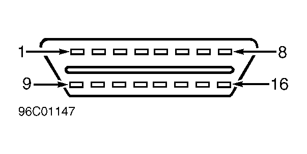
- Disconnect harness connector No. 1. Inspect connector for damage or corrosion and repair if necessary. Measure resistance between Data Link Connector (DLC) pin No. 2 (Tan/Orange wire) and harness connector No. 1 Tan/Orange wire terminal. See Fig 1
. If resistance is less than 5 ohms, go to next step. If resistance is 5 ohms or more, replace circuit No. 914 (Tan/Orange wire) and circuit No. 915 (Pink/Light Blue wire).
 Courtesy of FORD MOTOR CO.
 Courtesy of FORD MOTOR CO.
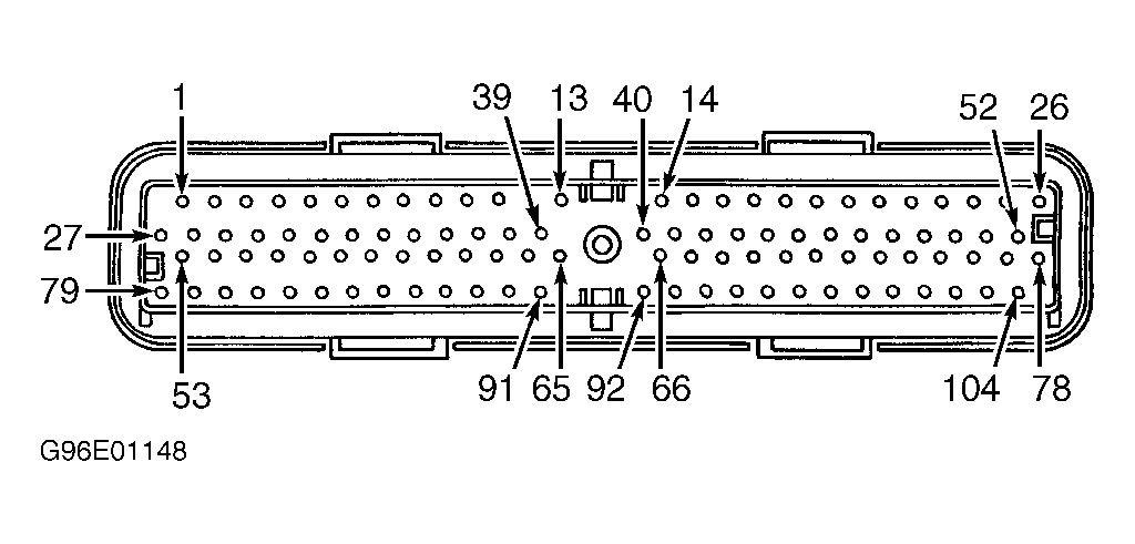
- Disconnect PCM 104-pin connector. Inspect pin No. 16 and circuit (Tan/Orange wire) for damage or corrosion. See Fig 2
. Repair if necessary. If circuit is okay, go to next step.
- Measure resistance between PCM connector pin No. 16 and harness connector No. 1 Tan/Orange wire terminal. If resistance is less than 5 ohms, replace PCM. If resistance is 5 ohms or more, replace circuit No. 914 (Tan/Orange wire) and circuit No. 915 (Pink/Light Blue wire) between PCM connector pin No. 16 and harness connector.
- Disconnect harness connector No. 1. Inspect connector and pin No. 7 (Pink/Light Blue wire) for damage or corrosion. If any faults are found, repair as necessary. If no faults are found, go to next step.
- Measure resistance between Data Link Connector (DLC) pin No. 10 (Pink/Light Blue wire) and harness connector No. 1 Pink/Light Blue wire terminal. If resistance is less than 5 ohms, go to next step. If resistance is 5 ohms or more, replace circuit No. 914 (Tan/Orange wire) and circuit No. 915 (Pink/Light Blue wire).
- Disconnect PCM 104-pin connector. Inspect pin No. 15 and circuit (Pink/Light Blue wire) for damage or corrosion. Repair if necessary. If circuit is okay, go to next step.
- Measure resistance between PCM connector pin No. 15 and harness connector No. 1 Pink/Light Blue wire terminal. If resistance is less than 5 ohms, replace circuit No. 914 (Tan/Orange wire) and circuit No. 915 (Pink/Light Blue wire) between PCM connector and harness connector C1. If resistance is 5 ohms or more, no faults are present at this time. Reconnect all components and verify symptom/fault code are present.
 Courtesy of FORD MOTOR CO.