Engine Controls - Sensor Operating Range Charts: Introduction: Notes
Sensor operating range information can help determine if a sensor is out of calibration. An out-of-calibration sensor may not set a trouble code, but it may cause driveability problems.
NOTE:
All voltage tests should be performed with a Digital Volt-Ohmmeter (DVOM) with a minimum 10-megohm input impedance, unless stated otherwise in test procedure.
AIR VALVE COOLANT TEMPERATURE SENSOR TEST
| Temperature °F (°C) |
Valve Position |
| 140 (60) |
Fully Closed |
COOLANT TEMPERATURE SENSOR RESISTANCE
| Temperature °F (°C) |
Resistance Ohms |
| -40 (-40) |
100,700 |
| 0 (-18) |
25,000 |
| 20 (-7) |
13,500 |
| 40 (4) |
7,500 |
| 68 (20) |
3,400 |
| 100 (38) |
1,800 |
| 160 (70) |
450 |
| 212 (100) |
185 |
MAP SENSOR VOLTAGE TEST
| Altitude Feet (Meters) |
Signal Voltage |
| Below 1,000 (304) |
3.8-5.5 |
| 1,000-2,000 (304-610) |
3.6-5.3 |
| 2,000-3,000 (610-914) |
3.5-5.1 |
| 3,000-4,000 (914-1219) |
3.3-5.0 |
| 4,000-5,000 (1219-1524) |
3.2-5.8 |
| 5,000-6,000 (1524-1829) |
3.0-4.6 |
| 6,000-7,000 (1829-2133) |
2.9-4.5 |
| 7,000-8,000 (2133-2438) |
2.8-4.3 |
| 8,000-9,000 (2438-2473) |
2.6-4.2 |
| 9,000-10,000 (2473-3048) |
2.5-4.0 |
MANIFOLD AIR TEMPERATURE (MAT) SENSOR RESISTANCE TEST
| Temperature °F (°C) |
Resistance Ohms |
| -40 (-40) |
100,700 |
| 0 (-18) |
25,000 |
| 20 (-7) |
13,500 |
| 40 (4) |
7,500 |
| 68 (20) |
3,400 |
| 100 (38) |
1,800 |
| 160 (70) |
450 |
| 212 (100) |
185 |
OXYGEN SENSOR VOLTAGE TEST
| Condition |
Volt |
| Lean |
.1 |
| Rich |
.9 |
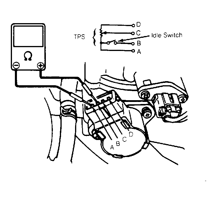
THROTTLE POSITION SENSOR (TPS) RESISTANCE TEST (METRO A/T ONLY)
| Condition |
Resistance (Ohms) |
| Between Terminals A-B |
Continuity |
| Between Terminals A-B |
No Continuity |
| Between Terminals A-B |
Continuity |
| Between Terminals A-D |
4,370-8,130 |
| Between Terminals A-C |
240-1,140 |
| Between Terminals A-C |
3,170-6,600 |
 Courtesy of GENERAL MOTORS CORP.