Vehicle Speed Sensor
- Following procedure applies if Code 24 is stored in ECM or incorrect input from vehicle speed sensor is suspected.
- Check speedometer operation. If speedometer operates correctly, go to next step. Repair or replace speedometer if speedometer is not operating properly.
- Disconnect 12-pin connector from instrument cluster. Using ohmmeter, measure resistance between Black/Yellow wire of connector and ground. If resistance is less than .3 ohm, go to next step. If resistance is greater than .3 ohm, repair Black/Yellow wire between instrument cluster and ground connection, located behind instrument panel (above fuse block).
- Turn ignition on. Using voltmeter, measure voltage between Yellow wire of instrument cluster 12-pin connector and ground. If voltage is less than 5 volts, go to next step. If voltage is greater than 5 volts, go to step 8).
- Turn ignition off. Disconnect 24-pin connector from ECM, located under left side of instrument panel, near kick panel. Using ohmmeter, measure resistance between Yellow wire of ECM connector and instrument cluster connector.
- If resistance is greater than .3 ohm, repair open circuit in Yellow wire. If resistance is less than .3 ohm, go to next step.
- Connect ohmmeter between Yellow wire of 18-pin ECM connector and ground. If continuity exists, repair short to ground in Yellow wire. If no continuity exists, replace ECM.
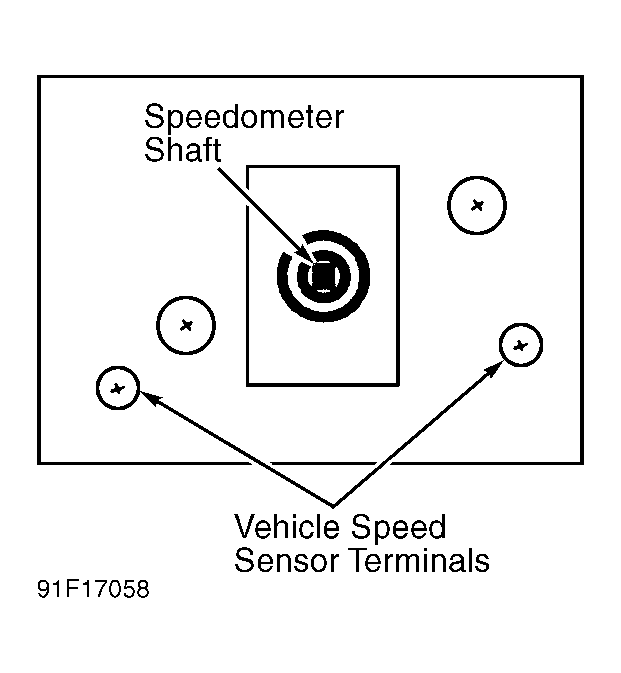
- Disconnect speedometer cable from speedometer. Connect ohmmeter across vehicle speed sensor terminals at speedometer head. See Fig 1
. Measure resistance while rotating speedometer head.
- If resistance decreases to less than 5 ohms 4 times per revolution, replace ECM. If resistance does not decrease to less than 5 ohms 4 times per revolution, replace speedometer.
 Courtesy of GENERAL MOTORS CORP.