Power Window System Inoperative
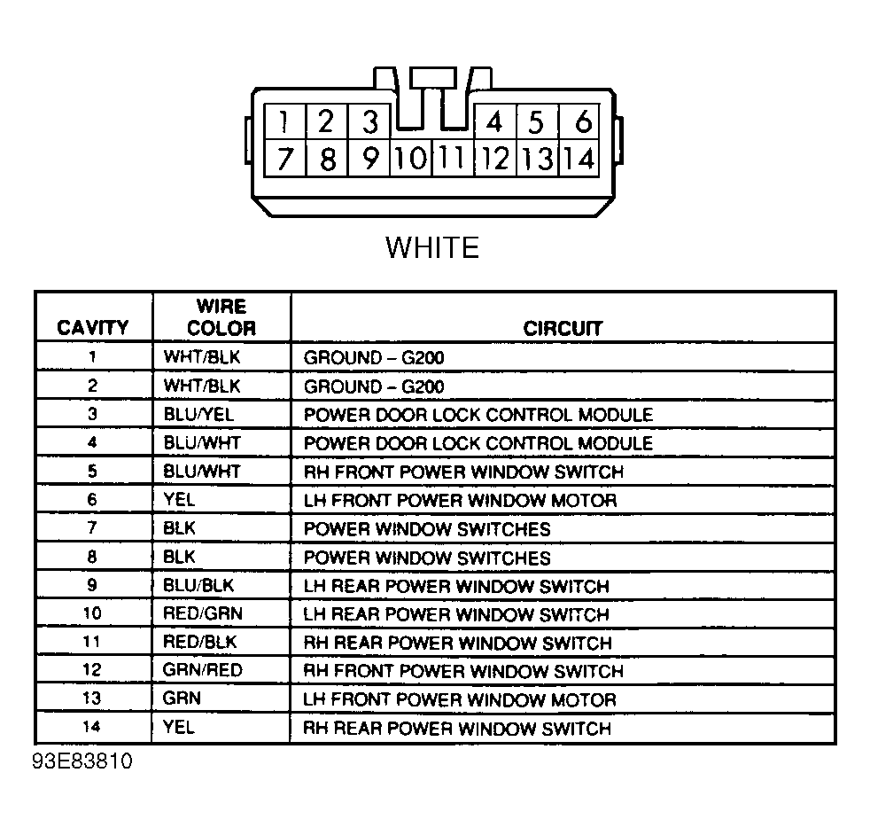
- Turn ignition on. Using a test light, probe power window master switch connector terminals No. 7 and 8 (Black wires at both terminals). See Fig 1
. If test light does not come on at both terminals or only comes on at one terminal, go to step 4). If test light comes on at both terminals, go to next step.
 Courtesy of GENERAL MOTORS CORP.
- Connect test light to battery voltage and probe power window master switch connector terminals No. 1 and 2 (White/Black wire on both terminals). See Fig 1
. If test light comes on at both terminals, replace power window master switch.
- If test light comes on at only one terminal, repair open in White/Black wire between terminal that did not come and splice S503 (located at left front door harness near power window master switch). If test light does not come on at either terminal, repair open in White/Black wire between splices S503 and S240 (located at instrument panel harness near accessory power relay).
- If test light does not come on at either terminal, go to next step. If test light comes on at only one terminal, repair open in Black wire between terminal that did not come on and splice S502 (located at left front door harness near power door lock actuator).
- Using a test light, probe power accessory relay connector terminal No. 4 (Black wire). If test light does not come on, go to next step. If test light comes on, repair open in Black wire between accessory power relay and splice S502.
- Using a test light, probe power accessory relay connector terminal No. 1 (White/Red wire). If test light comes on, go to next step. If test light does not come on, check for open in White/Red wire between accessory power relay and junction block No. 1. Repair wire as necessary. If wire is good, replace junction block No. 1.
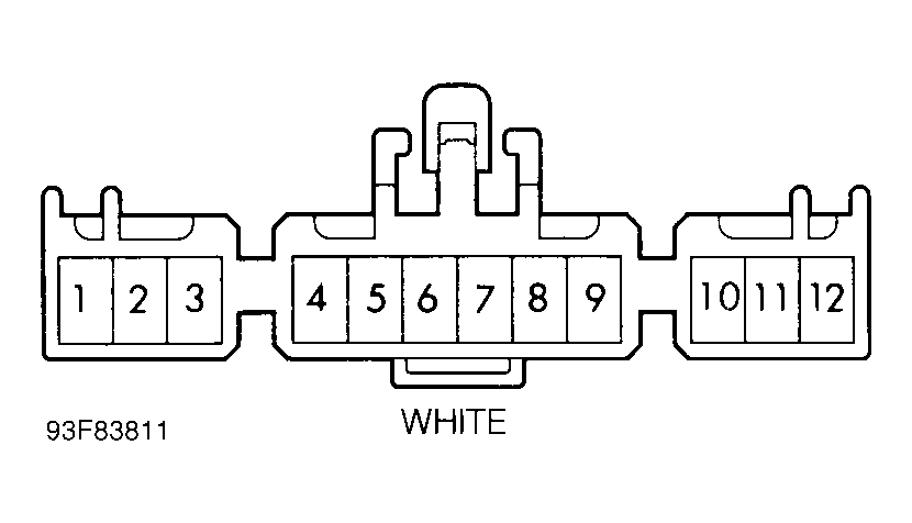
- Probe accessory power relay connector terminal No. 3 (Red/Blue wire). If test light comes on, go to step 9). If test light does not come on, connect a DVOM between audio alarm module connector terminal No. 9 (Red/Blue wire) and ground and check voltage. Refer to Fig. Fig 2
. If voltage is less than 10 volts, replace audio alarm module and retest system. If system remains inoperative, replace junction block No. 1.
 Courtesy of GENERAL MOTORS CORP.
- If voltage is greater than 10 volts, check for open in Red/Blue wire between audio alarm module and junction block No. 3. Check for open in Red/Blue wire between junction block No. 3 and power accessory relay. Repair wire as necessary. If wire is good, replace junction block No. 3.
- Connect test light from battery voltage to accessory power relay terminal No. 2 (White/Black wire). If test light comes on, replace accessory power relay. If test light comes on, check for open in White/Black wire between accessory power relay and junction connector No. 1. Check for open in White/Black wire between junction connector No. 1 and ground connector G200 (located behind left kick panel). Repair wire as necessary. If wire is good, replace junction connector No. 1.