Engine Controls - Sensor Operating Range Charts: Introduction
Sensor operating range information can help determine if a sensor is out of calibration. An out-of-calibration sensor may not set a trouble code, but it may cause driveability problems.
NOTE:
Unless stated otherwise in test procedure, perform all voltage tests using a Digital Volt-Ohmmeter (DVOM) with a minimum 10-megohm input impedance.
ENGINE COOLANT TEMPERATURE (ECT) SENSOR RESISTANCE
| Temperature - °F (°C) |
Ohms |
| 0 (-18) |
14,650 |
| 19 (-7) |
8100 |
| 39 (4) |
4780 |
| 70 (21) |
2350 |
| 100 (38) |
1250 |
| 160 (71) |
400 |
| 210 (99) |
190 |
EGR TEMPERATURE SENSOR RESISTANCE
| Temperature - °F (°C) |
Ohms |
| 68 (20) |
214,000-313,800 |
| 104 (40) |
90,900-125,700 |
| 140 (60) |
42,100-55,500 |
| 176 (80) |
21,100-26,500 |
| 212 (100) |
11,200-13,600 |
INTAKE AIR TEMPERATURE (IAT) SENSOR RESISTANCE
| Temperature - °F (°C) |
Ohms |
| 0 (-18) |
14,800 |
| 19 (-7) |
8250 |
| 39 (4) |
5200 |
| 70 (21) |
2500 |
| 100 (38) |
1300 |
| 160 (71) |
450 |
| 210 (99) |
200 |
Manifold Absolute Pressure (MAP) Sensor
For information on MAP sensor, see ENGINE SENSORS & SWITCHES in I - SYS/COMP TESTS article in the ENGINE PERFORMANCE Section.
OXYGEN SENSOR HEATER RESISTANCE
| Application |
Ohms |
| MFI (Calif. & New York) |
11.7-14.3 |
| TBI (Federal) |
3.0-5.5 |
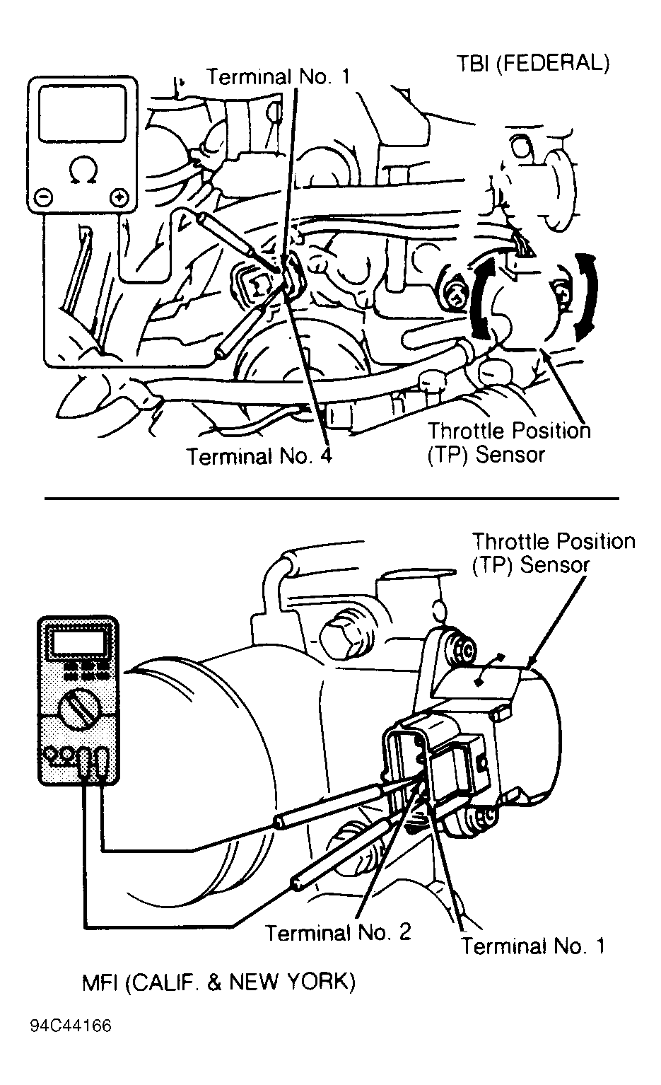
THROTTLE POSITION (TP) SENSOR RESISTANCE
| Application |
Ohms |
| TBI - Federal |
| Between Terminals 2 & 4 |
3500-6500 |
| Between Terminals 3 & 4 |
0-500 |
| Between Terminals 3 & 4 |
Infinity |
| Between Terminals 4 & 5 |
300-2000 |
| Between Terminals 4 & 5 |
2000-6500 |
| MFI - Calif. & New York |
| Between Terminals 1 & 3 |
3500-6500 |
| Between Terminals 1 & 2 |
0-500 |
| Between Terminals 1 & 2 |
Infinity |
| Between Terminals 1 & 4 |
300-2000 |
| Between Terminals 1 & 4 |
2000-6500 |
Vehicle Speed Sensor
For information on vehicle speed sensor, see ENGINE SENSORS & SWITCHES in I - SYS/COMP TESTS article in the ENGINE PERFORMANCE Section.
 Courtesy of GENERAL MOTORS CORP.