Shift Cable Adjustment
- Remove the center lower cover (see CENTER LOWER COVER REMOVAL/INSTALLATION
).
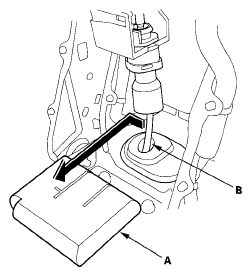
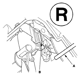
- Move the shift lever to R.
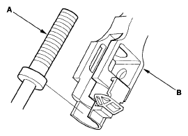
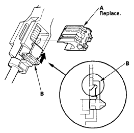
- Remove the shift cable insulator (A) from the shift cable (B).
 Courtesy of AMERICAN HONDA MOTOR CO., INC.
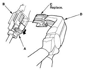
- Slide the lock tab (A) down on the shift cable end holder (B).
 Courtesy of AMERICAN HONDA MOTOR CO., INC.
- Grasp the shift cable lock (C) in the middle with angle-jaw needle-nose pliers (D), and remove it from the shift cable end and shift cable end holder. Do not pry the shift cable lock with a screwdriver, it may damage the shift cable end holder.
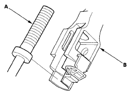
- Separate the shift cable end (A) from the shift cable end holder (B).
 Courtesy of AMERICAN HONDA MOTOR CO., INC.
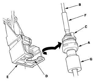
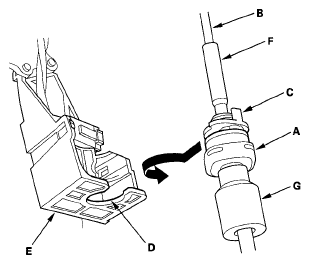
- Rotate the socket holder (A) on the shift cable (B) a quarter turn; the tab (C) on the socket holder will be in the opening (D) of the shift cable bracket (E). Then slide the socket holder out to remove the shift cable from the shift cable bracket. Do not remove the shift cable by twisting shift cable guide (F) and damper (G).
 Courtesy of AMERICAN HONDA MOTOR CO., INC.
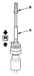
- Push the shift cable down until it stops, then release it. Pull the shift cable back one step so that the shift cable is in R. Do not hold the shift cable guide (A) to adjust the shift cable (B).
 Courtesy of AMERICAN HONDA MOTOR CO., INC.
- Turn the ignition switch to ON (II), and check that the R indicator comes on.
- Turn the ignition switch to LOCK (0).
- Insert a 6.0 mm (0.24 in.) pin (A) into the positioning hole (B) on the shift lever bracket through the positioning hole on the shift lever. The shift lever is secured in R.
 Courtesy of AMERICAN HONDA MOTOR CO., INC.
- Rotate the socket holder (A) on the shift cable (B) to face the tab (C) on the holder opposite the opening (D) in the shift cable bracket (E). Align the holder with the opening in the bracket, then slide the holder into the bracket. Rotate the socket holder a quarter turn to secure the shift cable. Do not install the shift cable by twisting the shift cable guide (F) and damper (G).
 Courtesy of AMERICAN HONDA MOTOR CO., INC.
- Install the shift cable end (A) in the shift cable end holder (B). Keep the shift cable end and end holder free of grease.
 Courtesy of AMERICAN HONDA MOTOR CO., INC.
- Install the new shift cable lock (A) to secure the shift cable end and shift cable end holder, then push the lock tab (B) up until it stops to lock joint.
 Courtesy of AMERICAN HONDA MOTOR CO., INC.
- Remove the 6.0 mm (0.24 in.) pin that was installed to hold the shift lever.
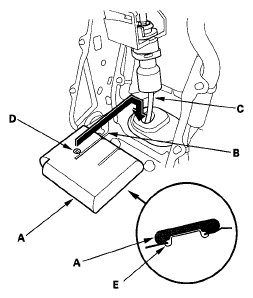
- Install the shift cable insulator (A) along the slot (B) over the shift cable (C), and position the shift cable in the left end (D) of the slot.
 Courtesy of AMERICAN HONDA MOTOR CO., INC.
- Push the insulator down so that it covers the shift cable grommet (E).
- Allow the all four wheels (4WD) or the front wheels (2WD) to rotate freely.
- Start the engine, and move the shift lever to each position. Check that the A/T gear position indicator follows the transmission range switch, and check the shift lever operation in each gear.
- Install the center lower cover (see CENTER LOWER COVER REMOVAL/INSTALLATION
).