Retrieving Codes
NOTE:
Ensure battery voltage is proper before retrieving codes.
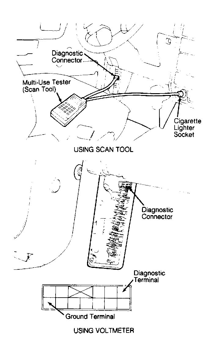
- Turn ignition switch to OFF position. Connect either a voltmeter between MPI diagnostic terminal and ground terminal of diagnostic connector, or multi-use tester (scan tool) to diagnostic connector and cigarette lighter. See Fig 1
. Turn ignition switch to ON position and disclosure of ECU memory (fault codes) will begin.
 Courtesy of HYUNDAI MOTOR CO.
- If using voltmeter to retrieve fault codes, it is important that voltage signals are accurately timed. Signals will appear in long and short pulses. Long pulses represent a numeral 10, whereas short pulses represent a numeral one. An example of fault code 15 would be one long pulse along with 5 short pulses.
- If using scan tool, and malfunction indicator light comes on while various checks are being made, check self-diagnostic output.
- After all checks have been made and/or trouble codes recorded, make necessary repairs. After repairs have been made, retest component(s) to ensure problem has been corrected.
DIAGNOSTIC CODE - EXCEL
| Code Number |
Fault Item |
Probable Cause |
See: |
| 11 |
O2 Sensor |
Fuel Pres., Injectors, Vacuum Leak, O2 Sensor |
Figure |
| 12 |
Airflow Sensor |
Airflow Sensor |
Figure |
| 13 |
Intake Air Temperature Sensor |
Intake Air Temperature Sensor |
Figure |
| 14 |
Throttle Position Sensor |
Throttle Position Sensor, Idle Switch |
Figure
and Figure |
| 15 |
Motor Position Sensor |
Motor Position Sensor |
Figure |
| 21 |
Coolant Temperature Sensor |
Coolant Temperature Sensor |
Figure |
| 22 |
Crank Angle Sensor |
Crank Angle Sensor |
Figure
and Figure |
| 23 |
TDC Sensor (No. 1 Cylinder) |
Distributor |
- |
| 24 |
Vehicle Speed Sensor Reed Switch |
Vehicle Speed Sensor Reed Switch |
- |
| 25 |
Barometric Pressure Sensor |
Barometric Pressure Sensor |
Figure |
| 41 |
Fuel Injector |
Injector Coil Resistance |
Figure
and Figure |
| 42 |
Fuel Pump |
Control Relay |
Figure |
| 43 |
EGR Temperature Sensor (Calif. Only) |
EGR Temp. Sensor, Vlv., Ctrl. Sol., Ctrl. Vac. |
Figure |
DIAGNOSTIC CODE - SONATA 2.4L
| Code Number |
Fault Item |
Probable Cause |
See: |
| 11 |
O2 Sensor |
Fuel Pres., Injectors, Vacuum Leak, O2 Sensor |
Figure |
| 12 |
Airflow Sensor |
Airflow Sensor |
Figure |
| 13 |
Intake Air Temperature Sensor |
Intake Air Temperature Sensor |
Figure |
| 14 |
Throttle Position Sensor |
Throttle Position Sensor, Idle Switch |
Figure |
| 15 |
Motor Position Sensor |
Motor Position Sensor |
Figure
and Figure |
| 21 |
Coolant Temperature Sensor |
Coolant Temperature Sensor |
Figure |
| 22 |
Crank Angle Sensor |
Crank Angle Sensor |
Figure
and Figure |
| 23 |
TDC Sensor (No. 1 Cylinder) |
Distributor |
- |
| 24 |
Vehicle Speed Sensor Reed Switch |
Vehicle Speed Sensor Reed Switch |
- |
| 25 |
Barometric Pressure Sensor |
Barometric Pressure Sensor |
Figure |
| 41 |
Fuel Injector |
Injector Coil Resistance |
Figure
and Figure |
| 42 |
Fuel Pump |
Control Relay |
Figure |
| 43 |
EGR Temperature Sensor (Calif. Only) |
EGR Temp. Sensor, Vlv., Ctrl. Sol., Ctrl. Vac. |
Figure |
DIAGNOSTIC CODE - SONATA 3.0L
| Code Number |
Fault Item |
Probable Cause |
See: |
| 11 |
O2 Sensor |
Fuel Pres., Injectors, Vacuum Leak, O2 Sensor |
Figure |
| 12 |
Airflow Sensor |
Airflow Sensor |
Figure |
| 13 |
Intake Air Temperature Sensor |
Intake Air Temperature Sensor |
Figure |
| 14 |
Throttle Position Sensor |
Throttle Position Sensor, Idle Switch |
Figure |
| 21 |
Coolant Temperature Sensor |
Coolant Temperature Sensor |
Figure |
| 22 |
Crank Angle Sensor |
Crank Angle Sensor |
Figure
and Figure |
| 23 |
TDC Sensor (No. 1 Cylinder) |
Distributor |
- |
| 24 |
Vehicle Speed Sensor Reed Switch |
Vehicle Speed Sensor Reed Switch |
- |
| 25 |
Barometric Pressure Sensor |
Barometric Pressure Sensor |
Figure |
| 41 |
Fuel Injector |
Injector Coil Resistance |
Figure
and Figure |
| 42 |
Fuel Pump |
Control Relay |
Figure |
| 43 |
EGR Temperature Sensor (Calif. Only) |
EGR Temp. Sensor, Vlv., Ctrl. Sol., Ctrl. Vac. |
Figure |