Sensor Range Charts
AIRFLOW SENSOR VOLTAGE TEST
| Between Terminals |
Volts |
| 3 & 6 |
2.7-3.2 |
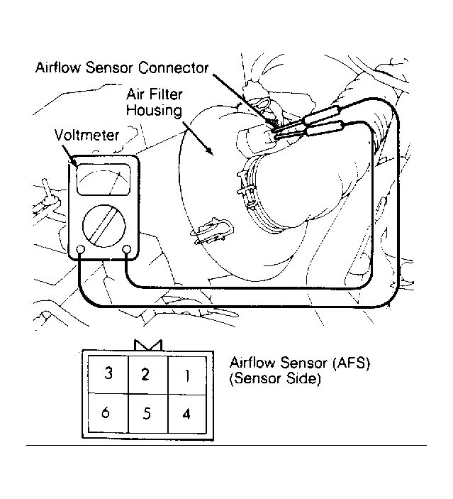 Courtesy of HYUNDAI MOTOR CO.
 COOLANT TEMP SENSOR RESISTANCE TEST
| Temperature °F (°C) |
Ohms |
| 32 (0) |
5900 |
| 68 (20) |
2500 |
| 104 (40) |
1100 |
| 176 (80) |
300 |
INTAKE AIR TEMP SENSOR RESISTANCE TEST
| Temperature °F (C) |
Ohms |
| 32 (0) |
5400-6600 |
| 68 (20) |
2330-2970 |
| 176 (80) |
310-430 |
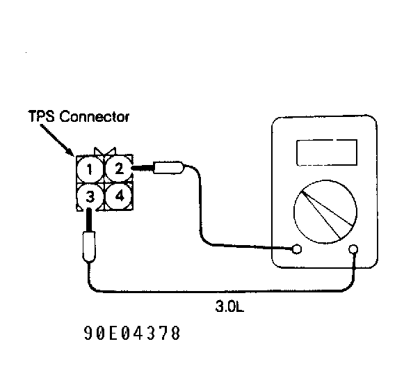
THROTTLE POSITION SENSOR (TPS) RESISTANCE TEST
| Throttle Position |
Ohms |
| Closed |
3500-6500 |
| Slowly Open to WOT |
500 to 3500-6500 |
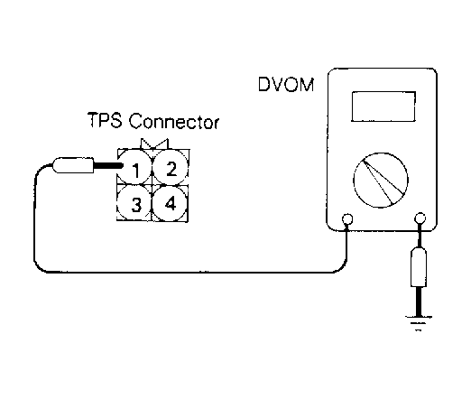 Courtesy of HYUNDAI MOTOR CO.
 Courtesy of HYUNDAI MOTOR CO.
 CRANK ANGLE SENSOR TEST
| Application |
Volts |
| 1.5L & 2.4L |
| Crank Angle Sensor |
1.8-2.5 |
| TDC Signal |
0.2-1.2 |
| 3.0L |
| Crank Angle Sensor |
2.0-2.5 |
| TDC Signal |
1.8-2.5 |
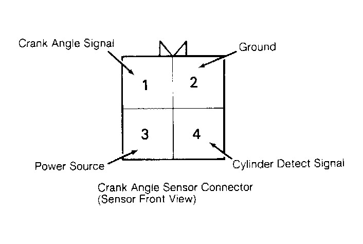 Courtesy of HYUNDAI MOTOR CO.
 OXYGEN (O2) SENSOR TEST
| Condition |
Specification |
| Increased RPM |
0.6 Volt Minimum |
| Sensor at 752°F (400°C) |
30 Ohms |
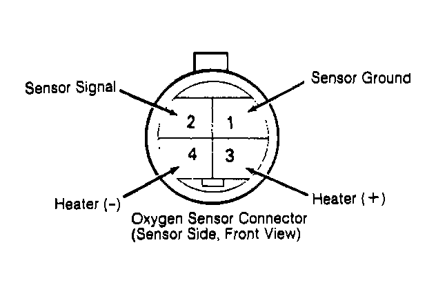 Courtesy of HYUNDAI MOTOR CO.