Fuel Injector Test: Maxima
- With engine running, listen for clicking sound at each injector. If clicking sound is present at each injector, system is functioning properly. If clicking sound is not present, go to next step.
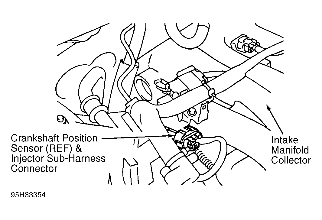
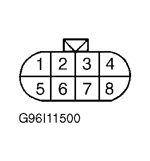
- Turn ignition off. To test left bank injectors, disconnect injector harness connector(s). To test right bank injectors, disconnect injector sub-harness connector. See Fig 1. Turn ignition on. On left bank injectors, measure voltage between ground and injector harness connector Red wire(s). On right bank injectors, measure voltage between injector sub-harness connector terminal No. 5. See Fig 2. Battery voltage should be present. If battery voltage is present, go to next step. If battery voltage is not present, check fusible link, ignition switch, and open or short in Red wire between ignition switch and injector(s) harness connector or sub-harness connector. Repair or replace as necessary. See WIRING DIAGRAMS
article.
- Turn ignition off. Disconnect PCM harness connector. Check continuity between specified PCM harness connector terminal and appropriate injector harness or sub-harness connector terminal. See INJECTOR CIRCUIT IDENTIFICATION (MAXIMA) table. If continuity exists in each circuit, go to next step. If continuity does not exist in any circuit, repair open or short in appropriate wire between PCM and injector harness or sub-harness connectors.
- Remove intake manifold collector from intake manifold. On right bank injectors, check continuity between injector sub-harness connector terminal No. 5 and each injector harness connector terminal No. 2 (Red wire). Also check continuity between injector harness connector terminal No. 1 and appropriate injector sub-harness connector terminal. See INJECTOR CIRCUIT IDENTIFICATION (MAXIMA) table. If continuity exists on each circuit, go to next step. If continuity does not exist on any circuit, repair open or short in appropriate wire.
- Check fuel injector(s). See FUEL INJECTOR . If fuel injectors are okay, check PCM harness connector terminals for damage or corrosion. Repair or replace as necessary.
INJECTOR CIRCUIT IDENTIFICATION (MAXIMA)
| Application |
PCM Terminal No. |
Wire Color |
| Injector No. 1 |
102 |
Red/Black |
| Injector No. 2 |
107 |
Red/Green |
| Injector No. 3 |
104 |
Red/Yellow |
| Injector No. 4 |
109 |
Black/Orange |
| Injector No. 5 |
111 |
Blue/White |
| Injector No. 6 |
114 |
Purple/Red |
 Courtesy of NISSAN MOTOR CO., U.S.A.
 Courtesy of NISSAN MOTOR CO., U.S.A.