Pathfinder & QX4
- Start engine. If engine starts, go to step 5. If engine does not start, go to next step.
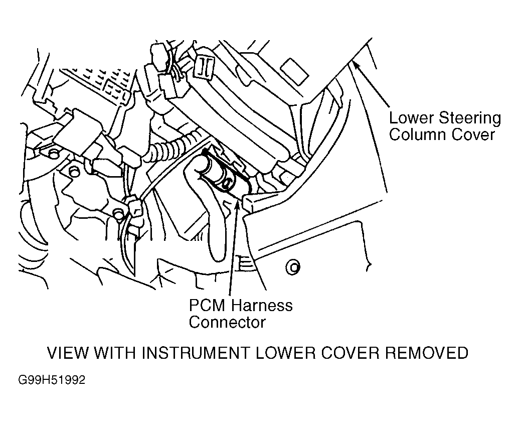
- Turn engine off and leave ignition on. Measure voltage between PCM harness connector terminal No. 24 (Black/White wire) and ground by backprobing. See Figure and Fig 1
. If battery voltage exists, go to next step. If battery voltage does not exist, repair open or short circuit. See appropriate diagram in WIRING DIAGRAMS article.
- Turn ignition off. Disconnect PCM harness connector. Check continuity between ground and PCM harness connector terminals No. 10, 19, 25, 32, 116 and 124. See Figure. If continuity exists on all wires, go to next step. If continuity does not exist on any wire, repair open ground circuit(s).
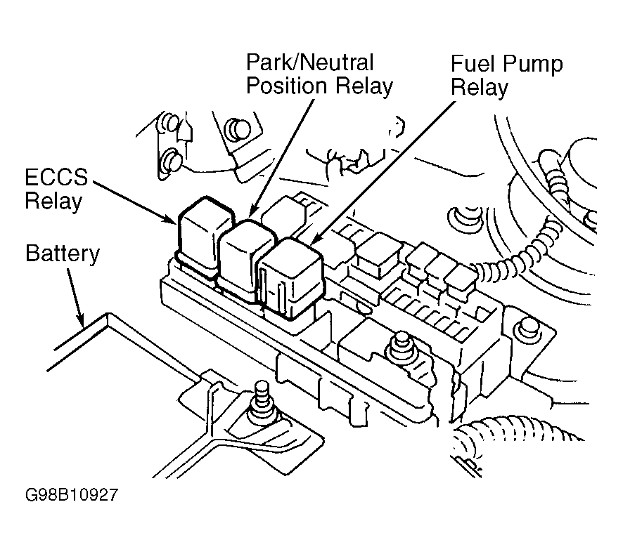
- Turn ignition off. Check continuity of Blue/Black wire between PCM harness connector terminal No. 4 and ECCS relay harness connector terminal No. 2. See Figure and Figure
. If continuity exists, go to step 12. If continuity does not exist, repair open in Blue/Black wire.
- Turn ignition on. Measure voltage between ground and PCM harness connector terminal No. 80 (White/Red wire) by backprobing. See Figure. If battery voltage exists, go to next step. If battery voltage does not exist, repair open or short circuit. See appropriate diagram in WIRING DIAGRAMS article.
- Turn ignition off. While turning ignition on then off, measure voltage between ground and PCM harness connector terminals No. 67, 72 and 117 (Black/White wires) by backprobing. Battery voltage should exist for a few seconds after ignition is turned off. If voltage is as specified, go to step 11. If battery voltage does not exist, go to next step. If battery voltage exists for more than a few seconds after ignition is turned off, go to step 10.
- Turn ignition off. Disconnect PCM harness connector. Disconnect ECCS relay. See Fig 2. Check continuity of Black/White wires between ECCS relay harness connector terminal No. 6 and PCM harness connector terminals No. 67, 72 and 117. See Figure and Figure
. If continuity exists on all wires, go to next step. If continuity does not exist on any wire, repair open in Black/White wire(s).
- Measure voltage between ground and ECCS relay harness connector terminals No. 1 and 7 (White/Red wires). See Figure. If battery voltage exists, go to next step. If battery voltage does not exist, repair open or short circuit. See appropriate diagram in WIRING DIAGRAMS article.
- Turn ignition off. Check continuity of Blue/Black wire between PCM harness connector terminal No. 4 and ECCS relay harness connector terminal No. 2. See Figure and Figure
. If continuity exists, go to next step. If continuity does not exist, repair open in Blue/Black wire.
- Check ECCS relay. See RELAYS under RELAYS & SOLENOIDS. Replace, if necessary and retest system. If relay is okay, go to next step.
- Turn ignition off. Disconnect PCM harness connector. Check continuity between ground and PCM harness connector terminals No. 10, 19, 25, 32, 116 and 124. See Figure. If continuity exists, go to next step. If continuity does not exist, repair open ground circuit(s).
- Check PCM harness connector terminals for damage or corrosion. Repair as necessary, reconnect all connectors and retest system.
 Courtesy of NISSAN MOTOR CO., U.S.A.
 Courtesy of NISSAN MOTOR CO., U.S.A.