Engine Controls Schematics
Engine Controls SchematicsGeneral Description
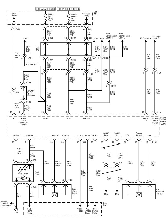
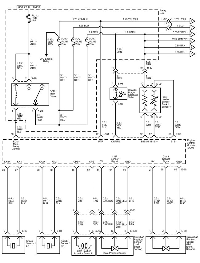
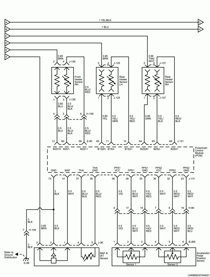
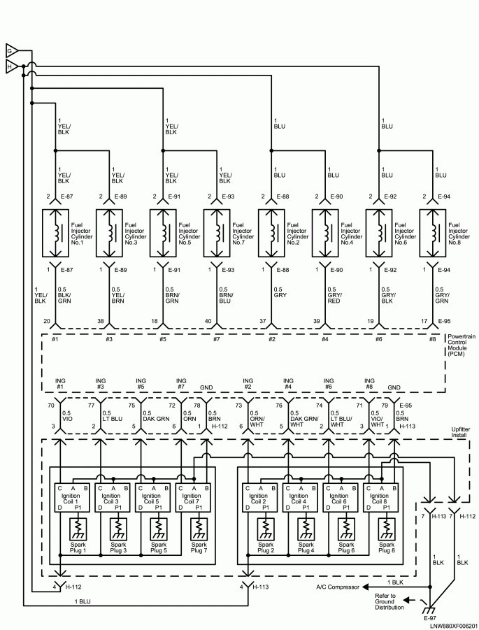
The circuit consists of the ignition switch, engine control module, stoplight switch, vehicle speed sensor, manifold absolute pressure sensor, throttle body, fuel injectors, oxygen sensors, ignition coils, camshaft position sensor, automatic transmission, knock sensor 1 and 2, crankshaft position sensor, engine coolant temperature sensor, mass airflow sensor, intake air temperature sensor and fuel pump relay.
The ECM performs the diagnostic function of the system. It can recognize operational problems, alert the driver through the Malfunction Indicator Light (MIL) and store a Diagnostic Trouble Code (DTC) which identify the problem areas to aid the technician in making repairs.
The ECM is designed to process various input information, and then sends the necessary electrical responses to control fuel delivery, spark timing, and other emission control systems.
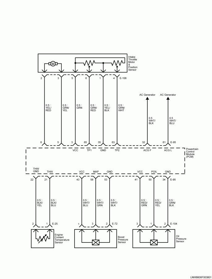
CIRCUIT DIAGRAM