Bus Bias Level Too Low Or Too High
- Disconnect scan tool. Turn ignition on. Using a DVOM, measure voltage between ground and Data Link Connector (DLC) connector terminal No. 3 (Violet/Brown wire). If voltage is 1.8-2.6 volts, go to next step. If voltage is not 1.8-2.6 volts, go to step 3
.
- Measure voltage between ground and DLC connector terminal No. 11 (White/Black wire). If voltage is not 1.8-2.6 volts, go to next step. If voltage is 1.8-2.6 volts, replace scan tool cable or scan tool. Perform BODY VERIFICATION TEST
under VERIFICATION TESTS.
- Reconnect scan tool to DLC. Select SYSTEM MONITOR then CCD BUS TEST on scan tool. Turn ignition off. Disconnect Transmission Control Module (TCM), if equipped. See Figure
. Turn ignition on. If scan tool does not display BUS OPERATIONAL, go to next step. If scan tool displays BUS OPERATIONAL, replace TCM. See TRANSMISSION CONTROL MODULE
under REMOVAL & INSTALLATION. Perform BODY VERIFICATION TEST
under VERIFICATION TESTS.
- Turn ignition off. Disconnect Powertrain Control Module (PCM). Turn ignition on. If scan tool does not display BUS OPERATIONAL, go to next step. If scan tool displays BUS OPERATIONAL, replace PCM. See POWERTRAIN CONTROL MODULE
under REMOVAL & INSTALLATION. Perform BODY VERIFICATION TEST
under VERIFICATION TESTS.
- Turn ignition off. Disconnect Compass/Mini-Trip Computer (CMTC), if equipped. Turn ignition on. If scan tool does not display BUS OPERATIONAL, go to next step. If scan tool displays BUS OPERATIONAL, replace CMTC. See OVERHEAD CONSOLE
under REMOVAL & INSTALLATION. Perform BODY VERIFICATION TEST
under VERIFICATION TESTS.
- Turn ignition off. Disconnect Remote Keyless Entry (RKE) module, if equipped. Turn ignition on. If scan tool does not display BUS OPERATIONAL, go to next step. If scan tool displays BUS OPERATIONAL, replace RKE module. See REMOTE KEYLESS ENTRY MODULE
under REMOVAL & INSTALLATION. Perform BODY VERIFICATION TEST
under VERIFICATION TESTS.
- Turn ignition off. Disconnect Sentry Key Immobilizer Module (SKIM). See Figure
. Turn ignition on. If scan tool does not display BUS OPERATIONAL, go to next step. If scan tool displays BUS OPERATIONAL, replace SKIM. See SENTRY KEY IMMOBILIZER MODULE
under REMOVAL & INSTALLATION. Perform BODY VERIFICATION TEST
under VERIFICATION TESTS.
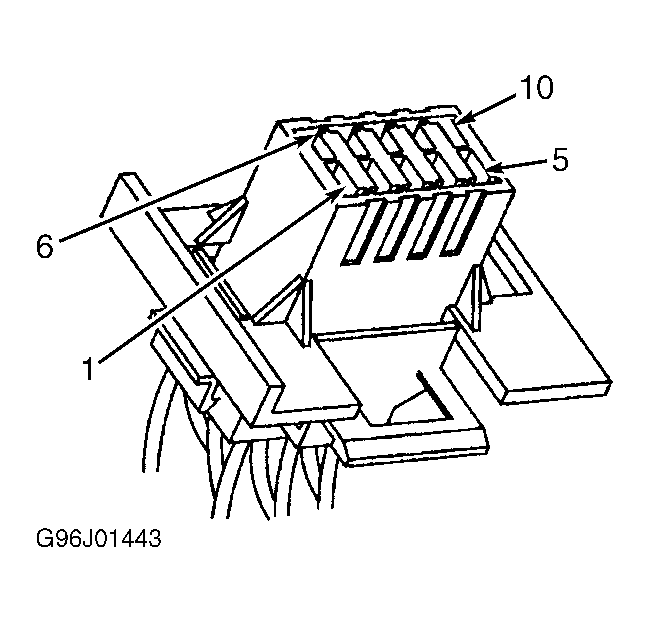
- Turn ignition off. Remove instrument cluster. Ensure interior lights are off. Disconnect scan tool from DLC. Using DVOM, measure resistance between ground and instrument cluster connector C1 terminal No. 6 (Black/Light Green wire). See Fig 1
. If resistance is less than 5 ohms, go to next step. If resistance is 5 ohms or greater, repair open in Black/Light Green wire between instrument cluster and ground. Perform BODY VERIFICATION TEST
under VERIFICATION TESTS.
- Ensure PCM, SKIM and ACM connectors are disconnected. Connect a jumper wire between ground and terminal No. 11 (White/Black wire) on DLC connector. Using DVOM, measure resistance between ground and instrument cluster connector C2 terminal No. 1 (White/Black wire). If resistance is less than 5 ohms, go to next step. If resistance is 5 ohms or greater, repair open in White/Black wire. Perform BODY VERIFICATION TEST
under VERIFICATION TESTS.
- Disconnect jumper wire. Measure resistance between ground and instrument cluster connector C2 terminal No. 1 (White/Black wire). If resistance is 1000 ohms or greater, go to next step. If resistance is less than 1000 ohms, repair short to ground in White/Black wire. Perform BODY VERIFICATION TEST
under VERIFICATION TESTS.
- Connect a jumper wire between ground and terminal No. 3 (Violet/Brown wire) on DLC connector. Using DVOM, measure resistance between ground and instrument cluster connector C2 terminal No. 2 (Violet/Brown wire). If resistance is less than 5 ohms, go to next step. If resistance is 5 ohms or greater, repair open in Violet/Brown wire between instrument cluster and PCM or TCM. Perform BODY VERIFICATION TEST
under VERIFICATION TESTS.
- Disconnect jumper wire. Measure resistance between ground and instrument cluster connector C2 terminal No. 2 (Violet/Brown wire). If resistance is less than 1000 ohms, repair short to ground in Violet/Brown wire. Perform BODY VERIFICATION TEST
under VERIFICATION TESTS. If resistance is 1000 ohms or greater, replace instrument cluster. See
appropriate INSTRUMENT PANELS article. Perform BODY VERIFICATION TEST
under VERIFICATION TESTS.
 Courtesy of CHRYSLER CORP.