Illuminated Entry Inoperative
- Turn ignition off. Using RKE transmitter, operate door locks. If door locks operate correctly, go to next step. If door locks do not operate correctly, go to step 4
.
- Check courtesy light operation by opening and closing doors, and using dash switch. If courtesy lights operate correctly, go to next step. If courtesy lights do not operate, diagnose interior lighting. See appropriate wiring diagram in
ILLUMINATION/INTERIOR LIGHTS article.
- Ensure ignition is off. Disconnect RKE module connector. RKE module is mounted in roof or overhead console. See COMPONENT LOCATIONS
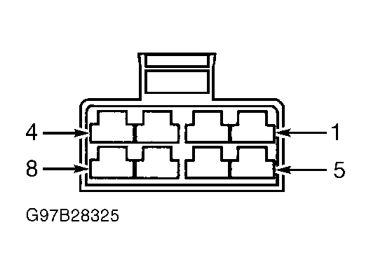
. Close all doors. Connect a jumper wire between ground and RKE module connector terminal No. 1 (Yellow wire). See Figure
. If courtesy lights illuminate, replace RKE module. See OVERHEAD CONSOLE
under REMOVAL & INSTALLATION. Perform BODY VERIFICATION TEST
under VERIFICATION TESTS. If courtesy lights do not illuminate, repair open in Yellow wire. Perform BODY VERIFICATION TEST
under VERIFICATION TESTS.
- Remove RKE transmitter batteries. Using DVOM, measure voltage of batteries. If voltage is greater than 3 volts, go to next step. If voltage is less than 3 volts, replace batteries. Perform BODY VERIFICATION TEST
under VERIFICATION TESTS.
- Using scan tool, program transmitter. Follow scan tool instructions. Using RKE transmitter, operate door locks. If door locks do not operate correctly, go to next step. If door locks operate correctly, test is complete.
- Disconnect RKE module connector. RKE module is mounted in roof or overhead console. See COMPONENT LOCATIONS
. Using a DVOM, measure voltage between ground and RKE module connector terminal No. 2 (Pink wire). See Figure
. If voltage is 10 volts or greater, go to next step. If voltage is less than 10 volts, repair open in Pink wire. Perform BODY VERIFICATION TEST
under VERIFICATION TESTS.
- Connect a jumper wire between ground and RKE module connector terminal No. 5 (Dark Blue wire). If door lock motor operates, remove jumper wire and go to next step. If door lock motor does not operate, go to step 10
.
- Connect a jumper wire between ground and RKE module connector terminal No. 11 (Light Blue/Red wire). If door lock motor does not operate, go to next step. If door lock motor operates, replace RKE module. See OVERHEAD CONSOLE
under REMOVAL & INSTALLATION. Perform BODY VERIFICATION TEST
under VERIFICATION TESTS.
- Remove passenger door panel. Disconnect passenger door module 8-pin connector. Connect a jumper wire between ground and RKE module connector terminals No. 5 (Dark Blue wire) and No. 11 (Light Blue/Red wire). Using DVOM, measure resistance between ground and passenger door module 8-pin connector terminal No. 2 (Dark Blue/Pink wire). See Fig 1
. If resistance is less than 5 ohms, go to step 12
. If resistance is 5 ohms or greater, repair open in Dark Blue/Pink or Dark Blue wire between door lock motor and door module. Perform BODY VERIFICATION TEST
under VERIFICATION TESTS.
- Remove passenger door panel. Disconnect passenger door module 8-pin connector. Connect a jumper wire between ground and RKE module connector terminals No. 5 (Dark Blue wire) and No. 11 (Light Blue/Red wire). Using DVOM, measure resistance between ground and passenger door module 8-pin connector terminal No. 2 (Dark Blue/Pink wire). See Fig 1
. If resistance is less than 5 ohms, go to next step. If resistance is 5 ohms or greater, repair open in Dark Blue/Pink or Dark Blue wire between RKE module and door module. Perform BODY VERIFICATION TEST
under VERIFICATION TESTS.
- Reconnect passenger door module 8-pin connector. Connect a jumper wire between ground and RKE module connector terminal No. 11 (Light Blue/Red wire). If door lock motor does not operate, go to next step. If door lock motor operates, replace RKE module. See OVERHEAD CONSOLE
under REMOVAL & INSTALLATION. Perform BODY VERIFICATION TEST
under VERIFICATION TESTS.
- Disconnect passenger door module 8-pin connector. Connect a jumper wire between ground and RKE module connector terminals No. 5 (Dark Blue wire) and No. 11 (Light Blue/Red wire). Using DVOM, measure resistance between ground and passenger door module 8-pin connector terminal No. 1 (Light Blue/Red wire). If resistance is less than 5 ohms, replace passenger door module. Perform BODY VERIFICATION TEST
under VERIFICATION TESTS. If resistance is 5 ohms or greater, repair open in Light Blue/Red wire between RKE module and door module. Perform BODY VERIFICATION TEST
under VERIFICATION TESTS.
 Courtesy of CHRYSLER CORP.