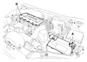
- Disconnect the battery negative cable (A).
- Remove the engine cover (B).
 Courtesy of KIA MOTORS AMERICA, INC.
- Remove RH front wheel.
- Remove RH side cover.
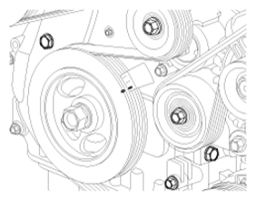
- Set No. 1 cylinder to TDC/compression.
 Courtesy of KIA MOTORS AMERICA, INC.
- Drain the engine oil, and then set a jack to the oil pan.
NOTE:
Place wooden block between the jack and engine oil pan.
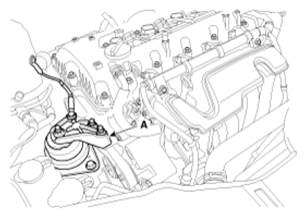
- Disconnect the ground line and then remove the engine mounting bracket (A).
 Courtesy of KIA MOTORS AMERICA, INC.
- Remove the drive belt (A) after turning the drive belt tensioner counterclockwise.
 Courtesy of KIA MOTORS AMERICA, INC.
 Courtesy of KIA MOTORS AMERICA, INC.
- Separate the power steering oil pump (A) from the bracket (HPS only). Refer to REPAIR PROCEDURES
.
- Remove the idler (B) and drive belt tensioner pulley (C).
 Courtesy of KIA MOTORS AMERICA, INC.
 Courtesy of KIA MOTORS AMERICA, INC.
- Remove the drive belt-tensioner (A).
 Courtesy of KIA MOTORS AMERICA, INC.
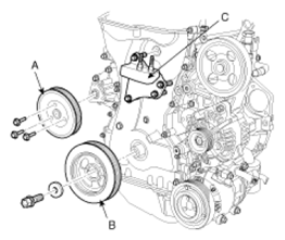
- Remove the water pump pulley (A), crankshaft pulley (B) and engine support bracket (C).
 Courtesy of KIA MOTORS AMERICA, INC.
NOTE:
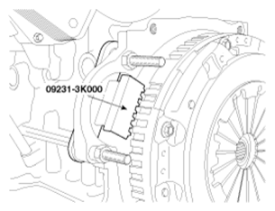
There are two methods to hold the ring gear when installing or removing the crankshaft damper pulley.
- Install the SST (09231-3K000) to hold the ring gear after removing the starter.
 Courtesy of KIA MOTORS AMERICA, INC.
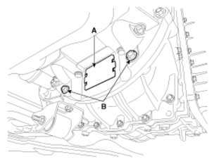
- Install the SST (09231-3D100) to hold the ring gear after removing the dust cover.
- Remove the dust cover (A) on the bottom of the ladder frame and unfasten the two transaxle mounting bolts (B).
 Courtesy of KIA MOTORS AMERICA, INC.
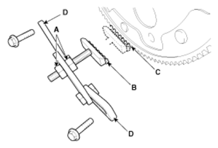
- Adjust the length of the holder nuts (A) so that the front plate of the holder (B) puts in the ring gear (C) teeth.
- Adjust the angle of the links (D) so that the two transaxle mounting bolts can be fastened to the original mounted holes.
 Courtesy of KIA MOTORS AMERICA, INC.
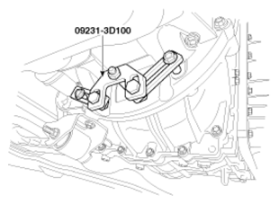
- Install the SST (09231-3D100) using the two transaxle mounting bolts and spacers. Tighten the bolts and nuts of the holder and links securely.
 Courtesy of KIA MOTORS AMERICA, INC.
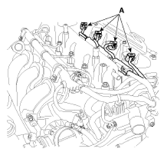
- Disconnect the ignition coil connectors (A) and remove the ignition coils.
 Courtesy of KIA MOTORS AMERICA, INC.
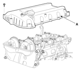
- Remove the cylinder head cover (A).
 Courtesy of KIA MOTORS AMERICA, INC.
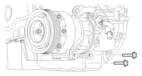
- Remove the compressor lower bolts.
 Courtesy of KIA MOTORS AMERICA, INC.
- Remove the compressor bracket.
- Remove the oil pan.
CAUTION:
Be careful not to damage the contact surfaces of cylinder block and oil pan.
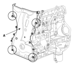
- Remove the timing chain cover (A) by gently prying the portions between the cylinder head and cylinder block.
 Courtesy of KIA MOTORS AMERICA, INC.
CAUTION:
Be careful not to damage the contact surfaces of cylinder block, cylinder head and timing chain cover.
- The key of crankshaft should be aligned with the mating face of main bearing cap. As a result of this, the piston of No. 1 cylinder is placed at the top dead center on compression stroke.
NOTE:
Before removing the timing chain, mark the timing chain with an identification based on the location of the sprocket because the identification mark on the chain for TDC (Top Dead Center) can be erased.
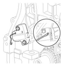
- Install a set pin after compressing the timing chain tensioner.
 Courtesy of KIA MOTORS AMERICA, INC.
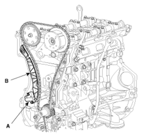
- Remove the timing chain tensioner (A) and timing chain tensioner arm (B).
 Courtesy of KIA MOTORS AMERICA, INC.
 Courtesy of KIA MOTORS AMERICA, INC.
- Remove the timing chain.
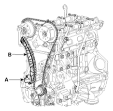
- Remove the timing chain guide (A).
 Courtesy of KIA MOTORS AMERICA, INC.
 Courtesy of KIA MOTORS AMERICA, INC.
- Remove the timing chain oil jet (A).
- Remove the crankshaft chain sprocket (B).
 Courtesy of KIA MOTORS AMERICA, INC.
- Remove the oil pump chain. Refer to LUBRICATION SYSTEM
.