FUEL INJECTOR (for Direct Injection): Removal
- PRECAUTION
CAUTION:
- Do not smoke or work near an open flame when handling the fuel system.
- Keep gasoline away from rubber or leather parts.
- Do not allow fuel to spray when removing the pipe between the high pressure side fuel pump assembly and the fuel injector assembly. The fuel in the pipe is highly pressurized.
- DISCHARGE FUEL SYSTEM PRESSURE
- Discharge fuel system pressure (See
FUEL SYSTEM )
- DISCONNECT CABLE FROM NEGATIVE BATTERY TERMINAL
NOTE:
When disconnecting the cable, some systems need to be initialized after the cable is reconnected (See
INITIALIZATION
).
- REMOVE INTAKE AIR SURGE TANK ASSEMBLY
- Remove the intake air surge tank assembly (See
REMOVAL
).
- REMOVE NO. 1 FUEL HOSE
(See
REMOVAL
)
- SEPARATE ENGINE WIRE
(See
REMOVAL )
- REMOVE NO. 3 COVER SUB-ASSEMBLY
(See
REMOVAL )
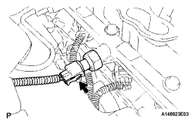
- REMOVE FUEL PRESSURE PULSATION DAMPER ASSEMBLY (for Direct Injection)
- Remove the fuel pressure pulsation damper assembly and No. 1 fuel pipe sub-assembly (See
REMOVAL )
- REMOVE NO. 3 FUEL PIPE SUB-ASSEMBLY
(See
REMOVAL )
- REMOVE NO. 2 FUEL PIPE SUB-ASSEMBLY
(See
REMOVAL )
- REMOVE NO. 1 ENGINE COVER SUB-ASSEMBLY
- Remove the No 1 engine cover sub-assembly
 Courtesy of © TOYOTA, LICENSE AGREEMENT TMS1002
- REMOVE NO. 2 ENGINE COVER SUB-ASSEMBLY LH
- Remove the No 2 engine cover sub-assembly LH
 Courtesy of © TOYOTA, LICENSE AGREEMENT TMS1002
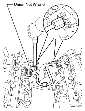
- REMOVE NO. 4 FUEL PIPE SUB-ASSEMBLY
- Using a 19 mm union nut wrench, remove the No 4 fuel pipe sub- assembly
 Courtesy of © TOYOTA, LICENSE AGREEMENT TMS1002
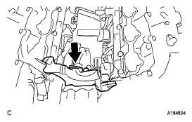
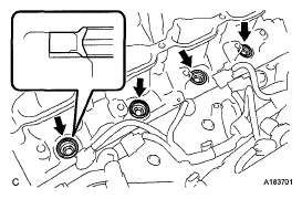
- REMOVE SEPARATOR CASE
- Disconnect the fuel pressure sensor connector
 Courtesy of © TOYOTA, LICENSE AGREEMENT TMS1002
- Remove the 4 bolts and separator case from the cylinder head.
 Courtesy of © TOYOTA, LICENSE AGREEMENT TMS1002
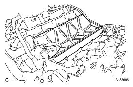
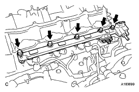
- REMOVE NO. 2 FUEL DELIVERY PIPE (for Direct Injection)
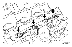
- Disconnect the 4 injector connectors.
 Courtesy of © TOYOTA, LICENSE AGREEMENT TMS1002
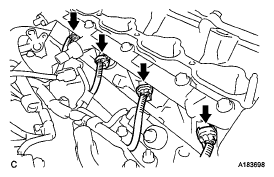
- Remove the 5 bolts and the No 2 fuel delivery pipe from the cylinder head
NOTE:
- Be extremely careful not to touch or strike the tips of the injectors.
- Pull the fuel delivery pipe straight without tilting it.
 Courtesy of © TOYOTA, LICENSE AGREEMENT TMS1002
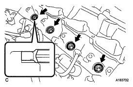
- Remove the 4 injector vibration insulators from the cylinder head.
 Courtesy of © TOYOTA, LICENSE AGREEMENT TMS1002
- REMOVE FUEL DELIVERY PIPE (for Direct Injection)
- Disconnect the 4 injector connectors
 Courtesy of © TOYOTA, LICENSE AGREEMENT TMS1002
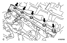
- Remove the 5 bolts and the fuel delivery pipe from the cylinder head.
NOTE:
- Be extremely careful not to touch or strike the tips of the injectors.
- Pull the fuel delivery pipe straight without tilting it.
 Courtesy of © TOYOTA, LICENSE AGREEMENT TMS1002
- Remove the 4 injector vibration insulators from the cylinder head
 Courtesy of © TOYOTA, LICENSE AGREEMENT TMS1002
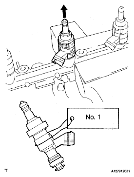
- REMOVE FUEL INJECTOR ASSEMBLY (for Direct Injection)
- Secure the delivery pipe between aluminum plates in a vise and pull the fuel injector assembly out in a straight line.
NOTE:
- Pull the fuel injector assembly straight out to avoid damage to the seal surface of the fuel delivery pipe and No. 2 fuel delivery pipe O-ring.
- For reinstallation, attach a tag or label to the injector shaft.
 Courtesy of © TOYOTA, LICENSE AGREEMENT TMS1002
- Remove the nozzle holder clamp from the fuel injector assembly
- Remove the O-ring, backup rings (No. 1, No. 2 and No. 3) and E-ring from the fuel injector
 Courtesy of © TOYOTA, LICENSE AGREEMENT TMS1002
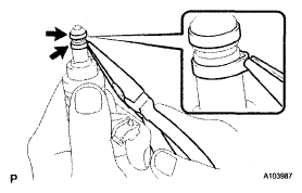
- REMOVE FUEL INJECTOR SEAL
- Using the tips of needle-nose pliers, pinch and pull one of the 2 fuel injector seals at several points to stretch it Repeat this for the other fuel injector seal
NOTE:
- Excessively pinching the fuel injector seal may damage the groove of the fuel injector assembly.
- If an injector is dropped or the tip of an fuel injector assembly is struck, replace it with a new one.
- Remove the 2 injector seals from the fuel injector assembly
 Courtesy of © TOYOTA, LICENSE AGREEMENT TMS1002