Pinpoint Test D: TCS Switch Does Not Operate Correctly
- D1 CHECK THE IC
- Connect the scan tool.
- Using the scan tool, monitor the TCS PID while cycling the Transmission Control Switch (TCS).
- Does the TCS PID cycle from depressed to not depressed?
- D2 CHECK BCM FUSE 42 (5A)
- Ignition OFF.
- Check fuse: Body Control Module (BCM) 42 (5A).
- Is the resistance less than 5 ohms?
- Yes
: GO to D3.
- No
: GO to D4.
- D3 CHECK THE TCS POWER CIRCUIT FOR AN OPEN
- Disconnect: Floor Shifter Harness C3245.
- Disconnect: BCM Fuse 42 (5A).
- Measure the resistance between floor shifter harness C3245-6, circuit CBP42 (GN) and the output side of BCM fuse 42 (5A).
- Is the resistance less than 5 ohms?
- Yes
: GO to D4.
- No
: REPAIR circuit CBP42 (GN) for an open. CLEAR the DTCs. TEST the system for normal operation.
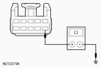
- D4 CHECK THE TCS POWER CIRCUIT FOR A SHORT TO GROUND
- Disconnect: C3245.
- Disconnect: BCM Fuse 42 (5A).
- Measure the resistance between floor shifter harness C3245-6, circuit CBP42 (GN) and ground.
 Courtesy of FORD MOTOR CO.
- Is the resistance greater than 10, 000 ohms?
- Yes
: GO to D5.
- No
: REPAIR circuit CBP42 (GN) for a short to ground. CLEAR the DTCs. TEST the system for normal operation.
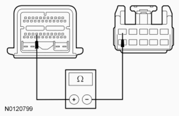
- D5 CHECK THE TCS SIGNAL CIRCUIT FOR AN OPEN
- Disconnect: PCM C175T.
- Measure the resistance between floor shifter harness C3245-5, circuit CET34 (BN/GN) and PCM C175T-31.
 Courtesy of FORD MOTOR CO.
- Is the resistance less than 5 ohms?
- Yes
: GO to D6.
- No
: REPAIR circuit CET34 (BN/GN) for an open. CLEAR the DTCs. TEST the system for normal operation.
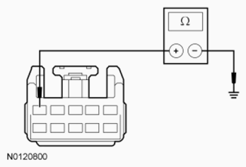
- D6 CHECK THE TCS SIGNAL CIRCUIT FOR A SHORT TO GROUND
- Measure the resistance between floor shifter harness C3245-5, circuit CET34 (BN/GN) and ground.
 Courtesy of FORD MOTOR CO.
- Is the resistance greater than 10, 000 ohms?
- Yes
: GO to D7.
- No
: REPAIR circuit CET34 (BN/GN) for a short to ground. CLEAR the DTCs. TEST the system for normal operation.
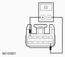
- D7 CHECK THE TCS
- Measure the resistance between floor shifter harness C3245-5 and C3245-6 component side, while cycling the TCS.
 Courtesy of FORD MOTOR CO.
- Is the resistance less than 5 ohms when pressed and greater than 10, 000 ohms when released?
- Yes
: REPLACE the PCM. PROGRAM the PCM with the latest calibration level. PERFORM the solenoid body strategy data download procedure, REFER to Solenoid Body Strategy in
AUTOMATIC TRANSMISSION - 6F50/6F55
or AUTOMATIC TRANSAXLE/TRANSMISSION - 6F35
.
TEST the system for normal operation.
- No
: INSPECT the floor shifter wiring harness for damage and repair as necessary. If the floor shifter wiring harness is not damaged, INSTALL a new selector lever knob. REFER to SELECTOR LEVER KNOB . CLEAR the DTCs. TEST the system for normal operation.