Reading and Clearing Diagnostic Trouble Codes
Procedures For Determining the Location of A MalfunctionMULTIPLEX COMMUNICATION SYSTEM
Outline
- If the controller area network (CAN) system is malfunctioning, read the DTCs of the following modules, using the SST (WDS or equivalent) to determine the malfunctioning system.
- PCM
- TCM
- ABS/TCS HU/CM
- Instrument cluster
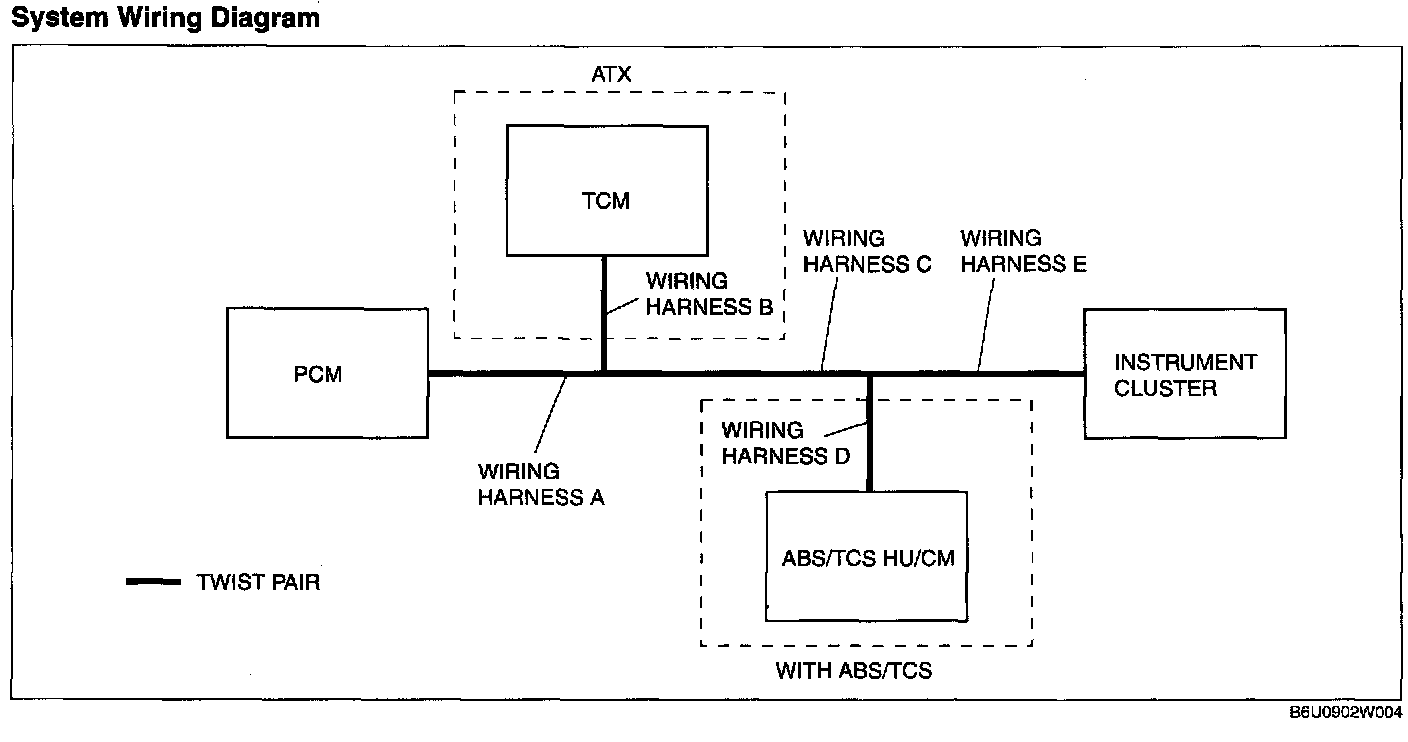
System Wiring Diagram
PCM
1. Check the display of DTC U0121 and/or U0155, using the SST (WDS or equivalent). (See DTC TABLE [MULTIPLEX COMMUNICATION SYSTEM].)
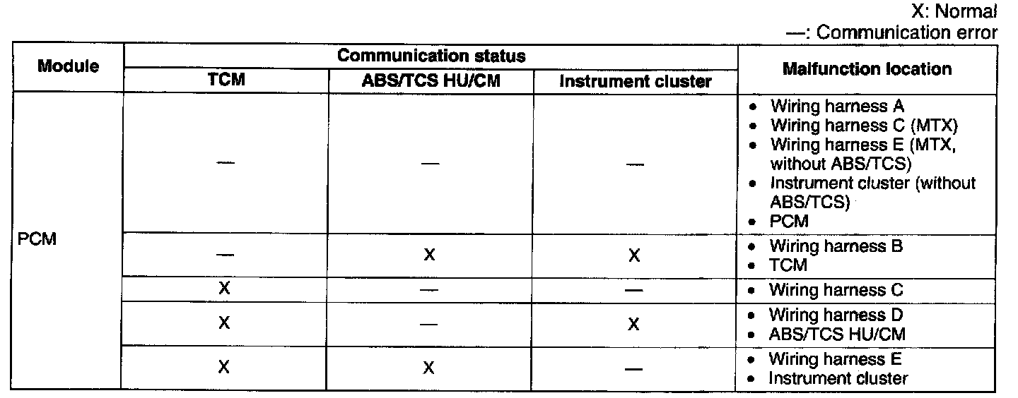
2. Referring to the given table, determine the malfunctioning part of the CAN system.
TCM
NOTE: The TCM is not able to read DTCs nor PIDs for confirming normal communication between ABS/TCS HU/CM and the instrument cluster. Therefore use the SST (WDS or equivalent) to read the PIDs from the ABS/TCS HU/CM and the instrument cluster in order to confirm normal communication between the two modules.
1. Check the display of DTC U0100, using the SST (WDS or equivalent). (See DTC TABLE [MULTIPLEX COMMUNICATION SYSTEM].)
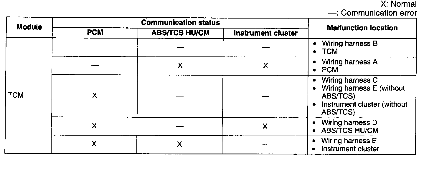
2. Referring to the given table, determine the malfunctioning part of the CAN system.
ABS/TCS HU/CM
NOTE: The ABS/TCS HU/CM is not able to read DTCs nor PIDs for confirming normal communication between instrument cluster. Therefore use the SST (WDS or equivalent) to read the PIDs from the instrument cluster in order to confirm normal communication between the two modules.
1. Access and monitor the "PCM_MSG" and "TCM_MSG" of PID using the SST (WDS or equivalent).
2. Referring to the PID/DATA MONITOR, confirm the display status of the PID. (See PID/DATA MONITOR TABLE [MULTIPLEX COMMUNICATION SYSTEM].)
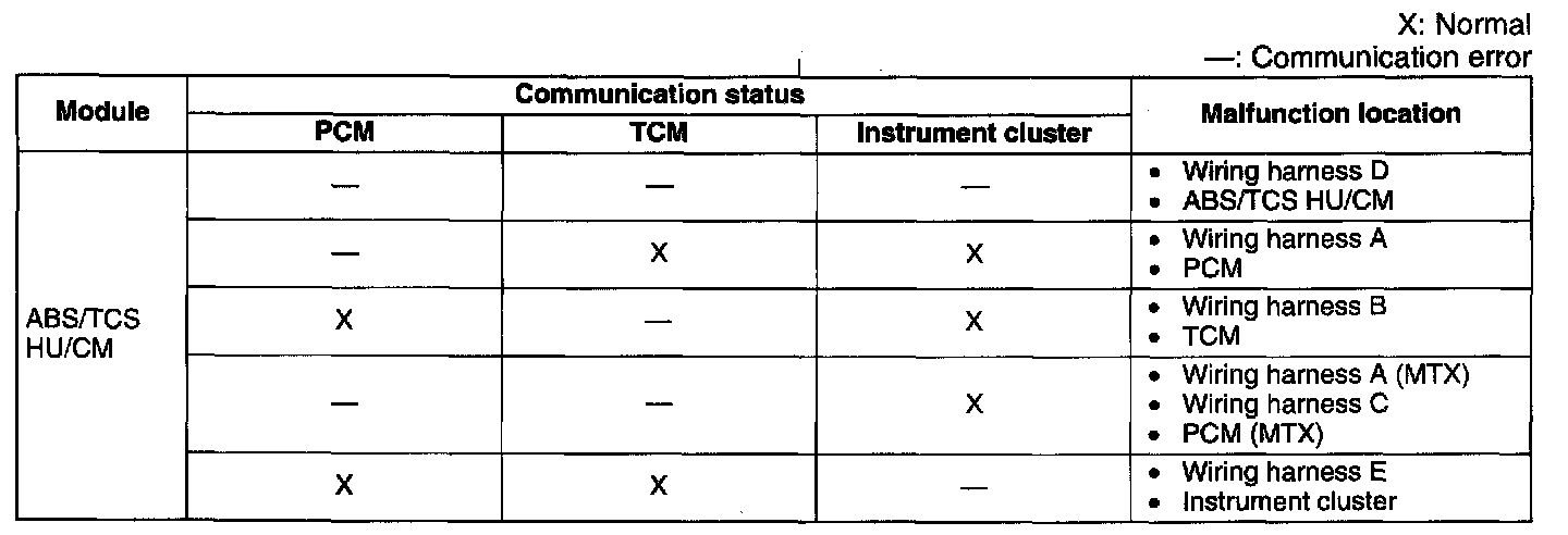
3. Referring to the given table, determine the malfunctioning part of the CAN system.
Instrument Cluster
1. Access and monitor the "PCM_MSG", "TCM_MSG" and "ABS_MSG" of PID using the SST (WDS or equivalent).
2. Referring to the PID/DATA MONITOR, confirm the display status of the PID. (See PID/DATA MONITOR TABLE [MULTIPLEX COMMUNICATION SYSTEM].)
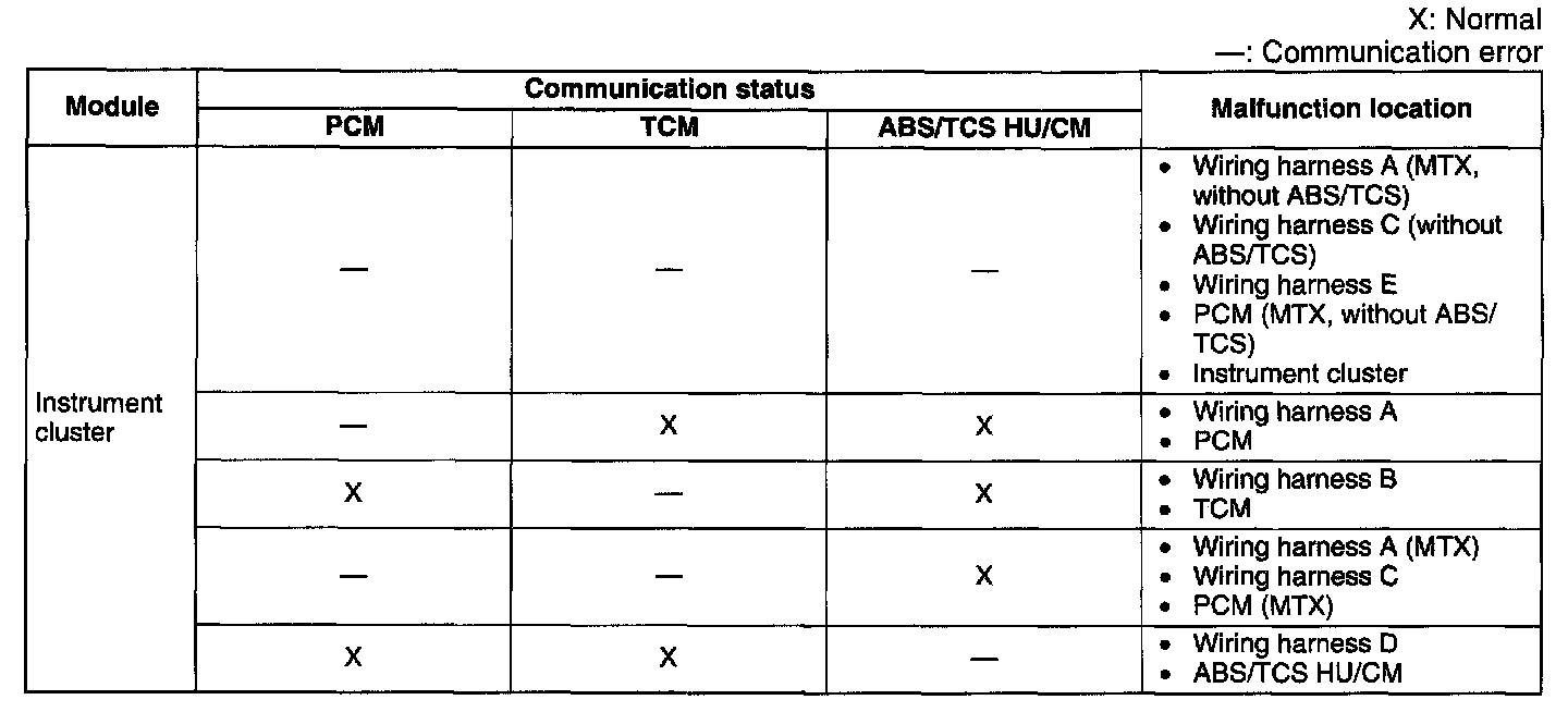
3. Referring to the given table, determine the malfunctioning part of the CAN system.