Fuel Charging Wiring Harness Removal / Installation - 2.3L
- Disconnect the negative battery cable. See
BATTERY DISCONNECT
.
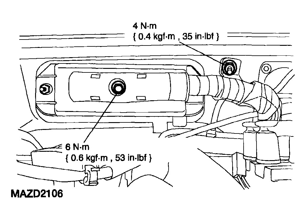
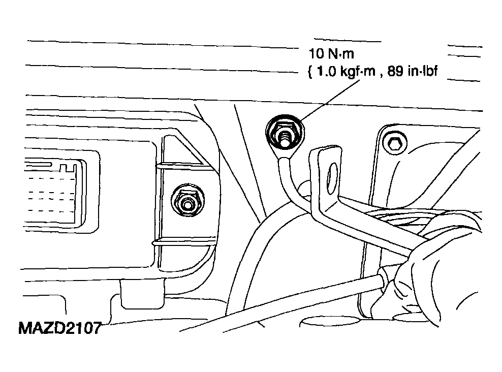
- Remove the upper intake manifold. See
INTAKE MANIFOLD REMOVAL / INSTALLATION - 2.3L
.
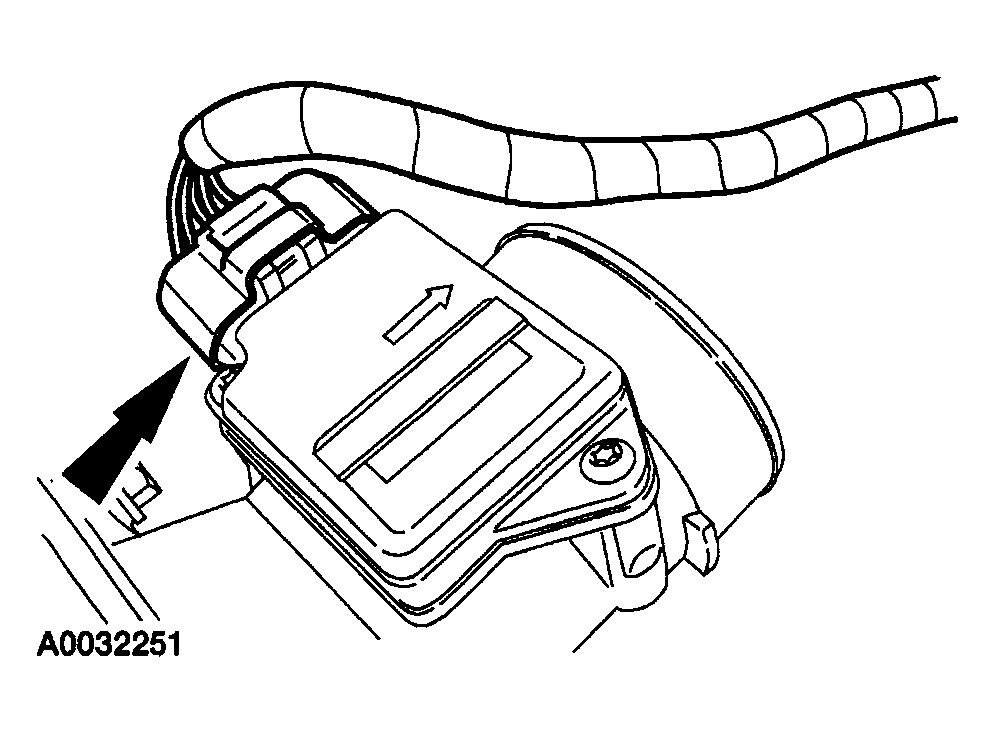
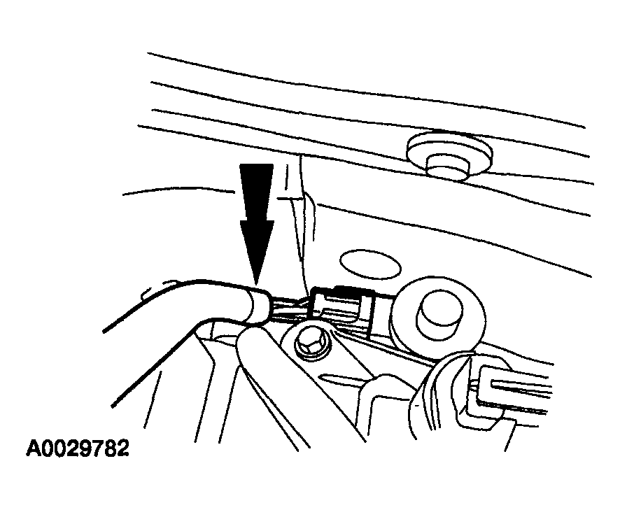
- Disconnect the mass airflow sensor electrical connector.
 Courtesy of MAZDA MOTORS CORP.
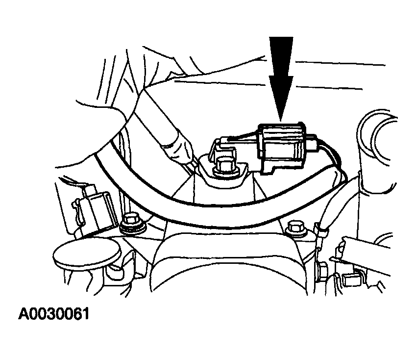
- Disconnect the right side of the wiring harness from the engine.
 Courtesy of MAZDA MOTORS CORP.
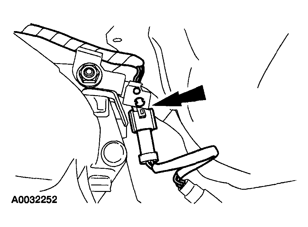
- Detach the cylinder head temperature (CHT) sensor boot.
 Courtesy of MAZDA MOTORS CORP.
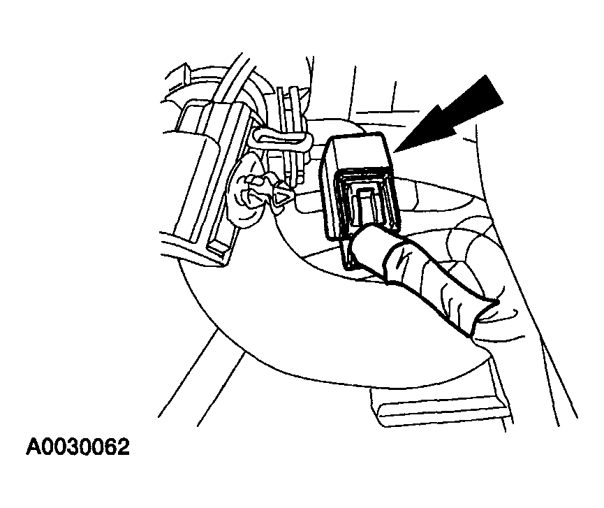
- Disconnect the CHT sensor electrical connector.
 Courtesy of MAZDA MOTORS CORP.
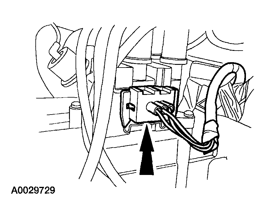
- Disconnect the powertrain control module (PCM) connector and the wiring harness clamp.
 Courtesy of MAZDA MOTORS CORP.
- Disconnect the PCM ground wire.
 Courtesy of MAZDA MOTORS CORP.
- Disconnect the ignition coil assembly electrical connector.
 Courtesy of MAZDA MOTORS CORP.
- Disconnect the water temperature sensor electrical connector.
 Courtesy of MAZDA MOTORS CORP.
- Disconnect the electric exhaust gas recirculation (EGR) (EEGR) valve electrical connector.
 Courtesy of MAZDA MOTORS CORP.
- Disconnect the camshaft position (CMP) sensor electrical connector.
 Courtesy of MAZDA MOTORS CORP.
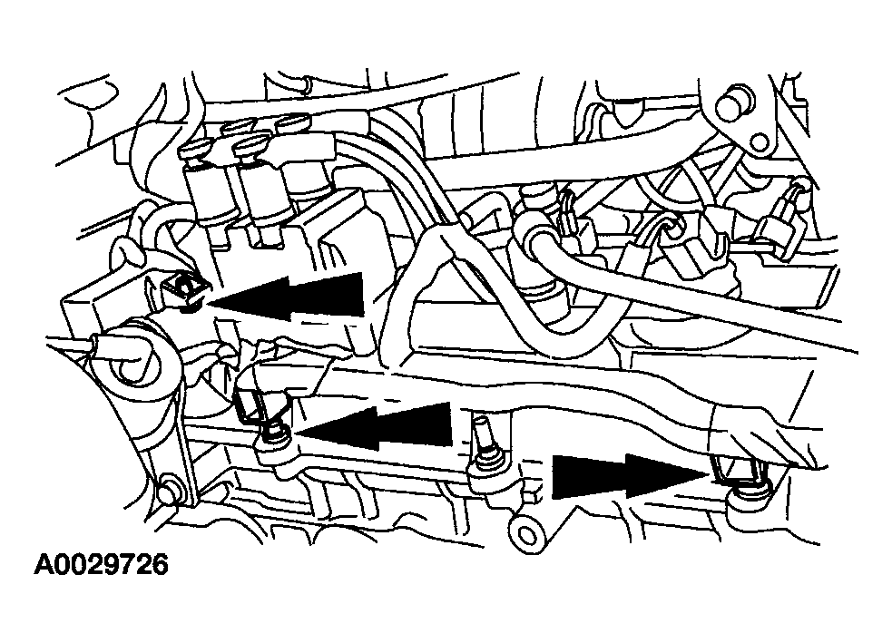
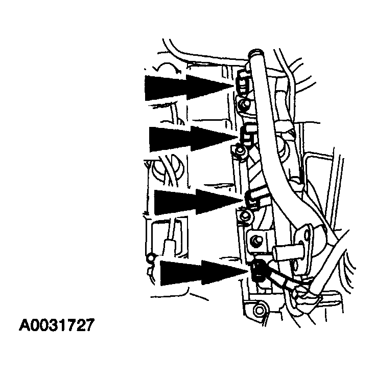
- Disconnect the fuel injectors.
 Courtesy of MAZDA MOTORS CORP.
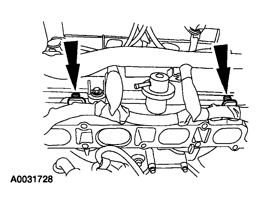
- Disconnect the fuel injector wiring from the fuel rail.
 Courtesy of MAZDA MOTORS CORP.
- Disconnect the heated oxygen sensor (HO2S) electrical connector and detach the connector from the bracket.
 Courtesy of MAZDA MOTORS CORP.
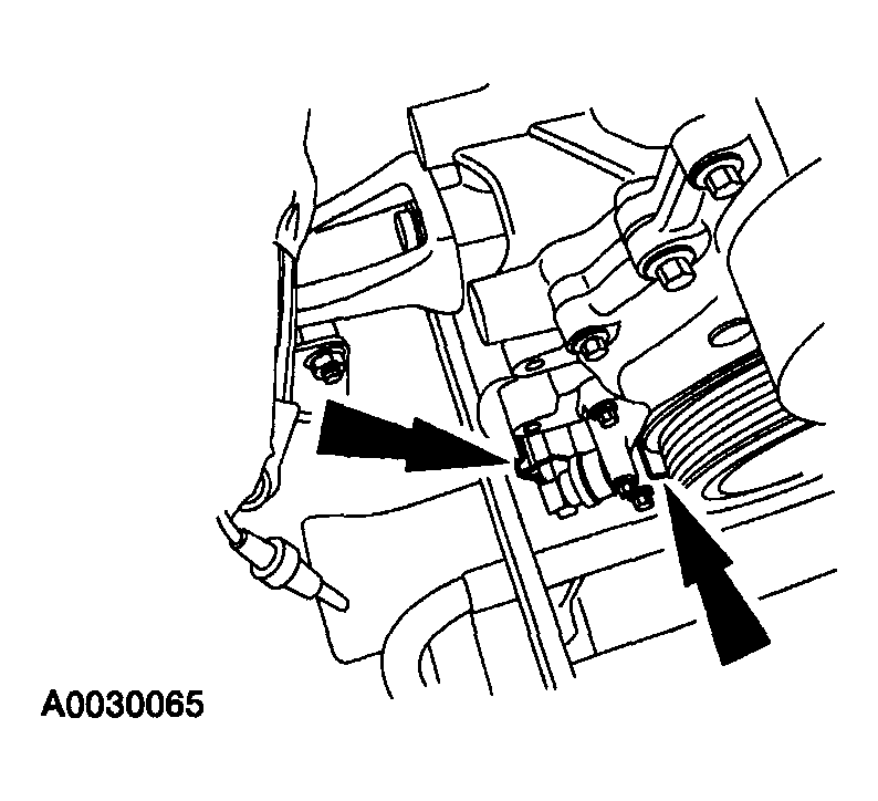
- Disconnect the transmission wiring harness.
 Courtesy of MAZDA MOTORS CORP.
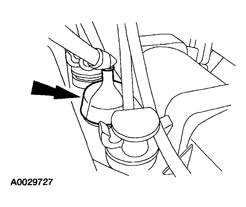
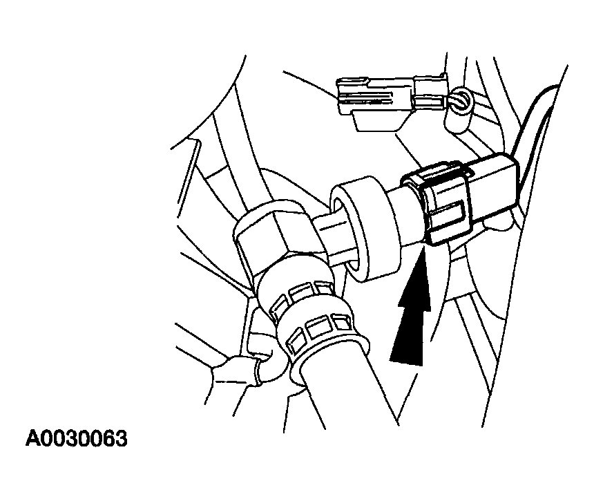
- Disconnect the thermostat housing electrical connector.
 Courtesy of MAZDA MOTORS CORP.
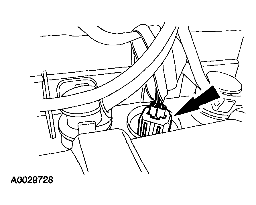
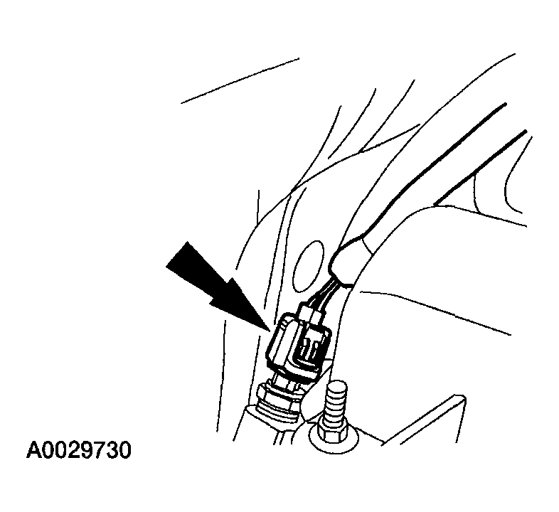
- Disconnect the power steering pressure (PSP) switch electrical connector.
 Courtesy of MAZDA MOTORS CORP.
- Disconnect the crankshaft position (CKP) sensor wiring from the front cover.
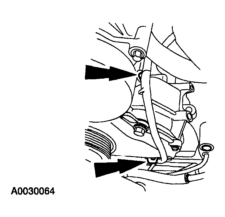 Courtesy of MAZDA MOTORS CORP.
- Disconnect the CKP sensor electrical connector and the wiring from the front cover.
 Courtesy of MAZDA MOTORS CORP.
- Remove the engine wiring harness from the engine compartment.
- To install, reverse the removal procedure.