Relay And Fuse Block Removal/Installation: Removal
- Remove the following parts.
- Plug hole plate. (See PLUG HOLE PLATE REMOVAL/INSTALLATION [MZR 2.5]
.)
- Battery cover. (See BATTERY REMOVAL/INSTALLATION [MZR 2.5]
.)
- Negative battery cable.
- MAF/IAT sensor connectors. (See INTAKE-AIR SYSTEM REMOVAL/INSTALLATION [MZR 2.5]
.)
- Air cleaner cover. (See INTAKE-AIR SYSTEM REMOVAL/INSTALLATION [MZR 2.5]
.)
- Resonance chamber.(See INTAKE-AIR SYSTEM REMOVAL/INSTALLATION [MZR 2.5]
.)
- Air hose. (See INTAKE-AIR SYSTEM REMOVAL/INSTALLATION [MZR 2.5]
.)
- Air cleaner element. (See INTAKE-AIR SYSTEM REMOVAL/INSTALLATION [MZR 2.5]
.)
- Air cleaner case. (See INTAKE-AIR SYSTEM REMOVAL/INSTALLATION [MZR 2.5]
.)
- Fresh-air duct (No. 3). (See INTAKE-AIR SYSTEM REMOVAL/INSTALLATION [MZR 2.5]
.)
- Positive battery cable. (See BATTERY REMOVAL/INSTALLATION [MZR 2.5]
.)
- Battery box. (See BATTERY REMOVAL/INSTALLATION [MZR 2.5]
.)
- Battery clamp. (See BATTERY REMOVAL/INSTALLATION [MZR 2.5]
.)
- Battery. (See BATTERY REMOVAL/INSTALLATION [MZR 2.5]
.)
- PCM cover No. 1. (See BATTERY REMOVAL/INSTALLATION [MZR 2.5]
.)
- PCM connectors. (See BATTERY REMOVAL/INSTALLATION [MZR 2.5]
.)
- Battery tray and PCM component. (See BATTERY REMOVAL/INSTALLATION [MZR 2.5]
.)
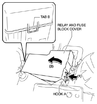
- While pressing hook A in the direction of arrow (1) in the figure, remove the relay and fuse block cover in the direction of arrow (2).
 Courtesy of MAZDA MOTORS CORP.
CAUTION:
- Detaching tab B without detaching hook A could damage the relay and fuse block cover. When removing the relay and fuse block cover, always detach hook A first.
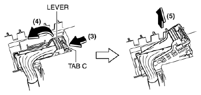
- With tab C pressed in the direction of the arrow (3), disconnect the relay and fuse block connector in the direction of the arrow (5) while raising the lever in the direction of the arrow (4) as shown in the figure.
 Courtesy of MAZDA MOTORS CORP.
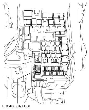
- Remove all of the relays and fuses except for the EHPAS 80A
fuse shown in the figure.
 Courtesy of MAZDA MOTORS CORP.
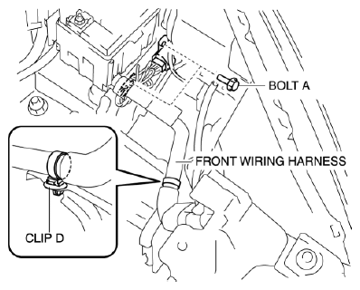
- Remove ground terminal securing bolt A which branches from the front wiring harness, and clip D securing the front wiring harness.
 Courtesy of MAZDA MOTORS CORP.
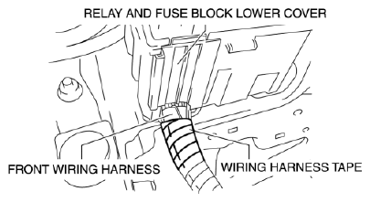
- Remove the relay and fuse block lower cover and the wiring harness tape securing the front wiring harness.
 Courtesy of MAZDA MOTORS CORP.
CAUTION:
- If a utility knife or nippers is used to remove the wiring harness tape, the blade tip could contact and sever the front wiring harness or damage the wiring cover. When using a utility knife or nippers to remove the wiring harness tape, be careful not to allow the blade tip to contact the front wiring harness.
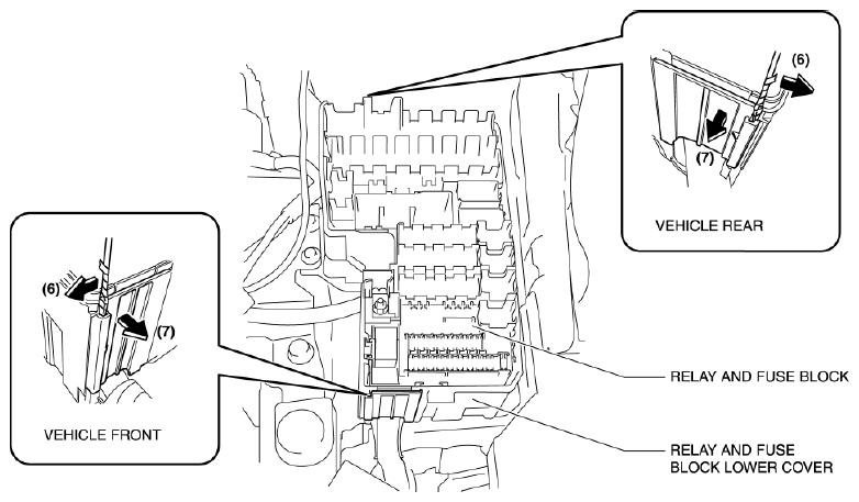
- Insert a flathead screwdriver or similar tool in the positions shown in the figure and pull the cover in the direction of the arrow (7) while moving it in the direction of the arrow (6), and open the cover.
 Courtesy of MAZDA MOTORS CORP.
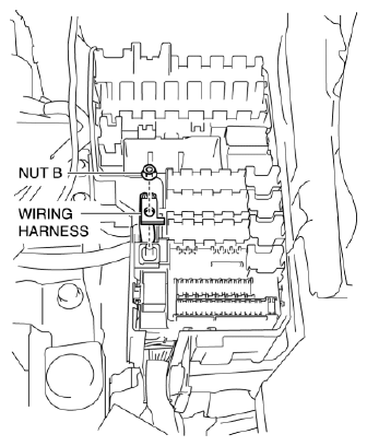
- Remove nut B and the wiring harness.
 Courtesy of MAZDA MOTORS CORP.
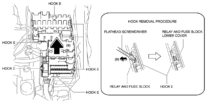
- Using a flathead screwdriver or similar tool, lift up the relay and fuse block in the direction of the arrow (9) while pressing the hook E in the direction of the arrow (8) shown in the figure, and remove it.
 Courtesy of MAZDA MOTORS CORP.
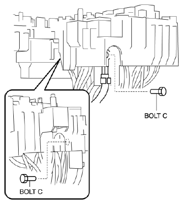
- Remove bolt C.
 Courtesy of MAZDA MOTORS CORP.
- Remove the EHPAS 80A
fuse.
- Set the removed relay and fuse block aside so that it does not scratch the vehicle and parts.
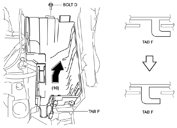
- Remove bolt D.
 Courtesy of MAZDA MOTORS CORP.
- Remove tab F from the wheel apron panel (front), and remove the relay and fuse block lower cover in the direction of the arrow (10) shown in the figure.