Test Preparation For DTC Readout
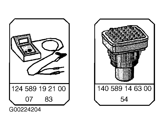
- Connect impulse counter scan tool and adapter or HHT to data link connector (X11/4). See Fig 1.
- Connect Yellow wire from impulse counter scan tool as follows:
- Socket 8
Base Module - BM (N16/1)
- Socket 6
ABS or ASR control module (N30 or N30/1)
- Socket 12
SPS control module (N49/1)
- Socket 11
ADS control module (N51)
- Socket 4
HFM-SFI control module (N3/4)
- Turn ignition ON.
- Read DTC memory for BM, ABS, ABS/ASR, SPS, ADS, HFM-SFI control modules.
 Courtesy of MERCEDES-BENZ OF NORTH AMERICA.