Test A: Locks Inoperative Using Key
- Lock and unlock door locks using master window/door lock switch. If door locks operate properly, go to next step. If door locks do not operate properly, see
POWER DOOR LOCKS - VILLAGER article for further testing information.
- Lock doors using driver and passenger key lock switch. If all doors lock from each key lock switch, go to step 6
. If doors do not lock from both key lock switches, go to next step. If doors do not lock from only one key lock switch, go to step 4
.
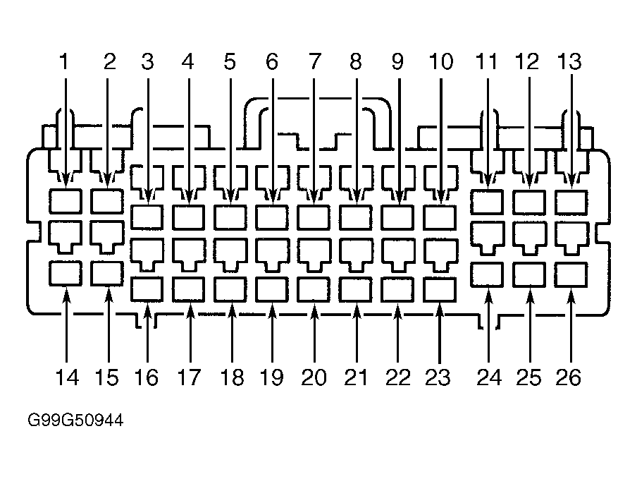
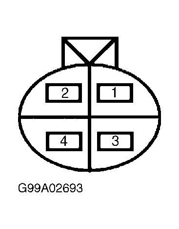
- Turn ignition off. Disconnect Smart Entry Control (SEC)/timer module Gray 26-pin connector C2032B located behind top center of dash. Remove driver door trim panel. Disconnect driver key lock switch Gray 4-pin connector C515 located in driver door. Measure resistance of Red wire between driver key lock switch connector C515 terminal No. 1 and SEC/timer module connector C2032B terminal No. 8. See Fig 1
and Fig 2
. If resistance is less than 5 ohms, replace SEC/timer module. Recheck system operation. If resistance is greater than 5 ohms, repair open in Red wire. Recheck system operation.
 Courtesy of FORD MOTOR CO.
 Courtesy of FORD MOTOR CO.
- Turn ignition off. Disconnect SEC/timer module Gray 26-pin connector C2032B located behind top center of dash. Disconnect inoperative key lock switch connector. Measure resistance of Red wire between suspect key lock switch connector and SEC/timer module connector C2032B terminal No. 8. See Fig 1
and Fig 2
. If resistance is less than 5 ohms, go to next step. If resistance is greater than 5 ohms, repair open in Red wire. Recheck system operation.
- Measure resistance between ground and suspect key lock switch Black wire terminal. If resistance is less than 5 ohms, replace appropriate key lock switch. Recheck system operation. If resistance is greater than 5 ohms, repair open in appropriate Black wire. Recheck system operation.
- Unlock all doors from driver, passenger and liftgate key lock switches by turning key twice within 5 seconds. If all doors locks are do not operative from one key lock switch, go to step 8
. If all door locks do not operate from more than one key lock switch, go to next step.
- Turn ignition off. Disconnect SEC/timer module Gray 26-pin connector C2032B. Disconnect driver key lock switch connector. Measure resistance of Red/Black wire between driver key lock switch connector terminal No. 2 and SEC/timer module connector C2032B terminal No. 21. See Fig 1
and Fig 2
. If resistance is less than 5 ohms, replace SEC/timer. Recheck system operation. If resistance is greater than 5 ohms, repair open in Red/Black wire. Recheck system operation.
- Turn ignition off. Disconnect SEC/timer module Gray 26-pin connector C2032B. Disconnect inoperative key lock switch connector. Measure resistance of Red/Black wire between inoperative key lock switch connector and SEC/timer module connector C2032B terminal No. 21. If resistance is less than 5 ohms, go to next step. If resistance is greater than 5 ohms, repair open in appropriate Red/Black wire. Recheck system operation.
- Measure resistance between ground and inoperative key lock switch connector Black wire terminal. See WIRING DIAGRAMS
. If resistance is less than 5 ohms, replace appropriate key lock switch. Recheck system operation. If resistance is greater than 5 ohms, repair open in appropriate Black wire. Recheck system operation.