Transaxle Support Insulator: Installation
- Install the bottom transaxle support insulator bolts.
- Tighten to 55 Nm (41 lb-ft).
 Courtesy of FORD MOTOR CO.
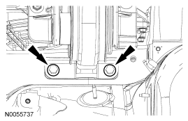
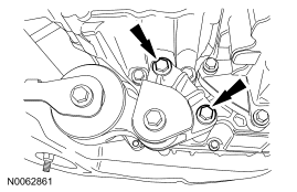
- Install the top transaxle support insulator bolts.
- Tighten to 55 Nm (41 lb-ft).
 Courtesy of FORD MOTOR CO.
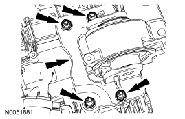
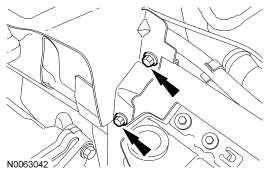
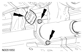
- Install the transaxle support insulator bracket and install the 4 transaxle support insulator bracket nuts.
- Tighten to 63 Nm (46 lb-ft).
 Courtesy of FORD MOTOR CO.
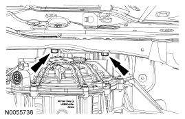
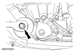
- Using the floor jack and Oil Pan Holding Fixture, raise the transaxle and install the transaxle support insulator through bolt.
- Tighten to 175 Nm (129 lb-ft).
 Courtesy of FORD MOTOR CO.
- Remove the floor jack and the Oil Pan Holding Fixture.
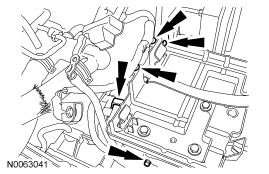
- Install the battery tray and bracket, install the battery tray bolt and nut.
- Tighten to 9 Nm (80 lb-in).
 Courtesy of FORD MOTOR CO.
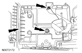
- Install the 2 lower battery tray bracket bolts.
- Tighten to 9 Nm (80 lb-in).
 Courtesy of FORD MOTOR CO.
- Attach the 5 pin-type wiring harness fasteners to the battery tray.
 Courtesy of FORD MOTOR CO.
- Install the battery. For additional information, refer to BATTERY, MOUNTING AND CABLES
article.
- Position the ACL assembly in place and install the 2 ACL assembly bracket bolts.
- Tighten to 11 Nm (97 lb-in).
 Courtesy of FORD MOTOR CO.
- Tighten the ACL outlet pipe clamp at the TB.
- Tighten to 5 Nm (44 lb-in).
 Courtesy of FORD MOTOR CO.
- Connect the engine breather to the ACL assembly.
 Courtesy of FORD MOTOR CO.
- Connect the MAF sensor electrical connector.
 Courtesy of FORD MOTOR CO.
- Position the roll restrictor in place and install the roll restrictor bolts.
- Tighten to 90 Nm (66 lb-ft).
 Courtesy of FORD MOTOR CO.
- Tighten the engine roll restrictor-to-subframe through bolt.
- Tighten to 90 Nm (66 lb-ft).
 Courtesy of FORD MOTOR CO.
- Install new exhaust seals, position the exhaust Y-pipe assembly in place and install 4 new exhaust Y-pipe assembly nuts.
- Tighten to 40 Nm (30 lb-ft).
 Courtesy of FORD MOTOR CO.
- Install a new exhaust seal, position the Y-pipe in the exhaust hanger and install 2 new exhaust flange nuts.
- Tighten to 40 Nm (30 lb-ft).
 Courtesy of FORD MOTOR CO.