Using Malfunction Indicator Light (MIL)
- Before entering on-board diagnostics, see SERVICE PRECAUTIONS
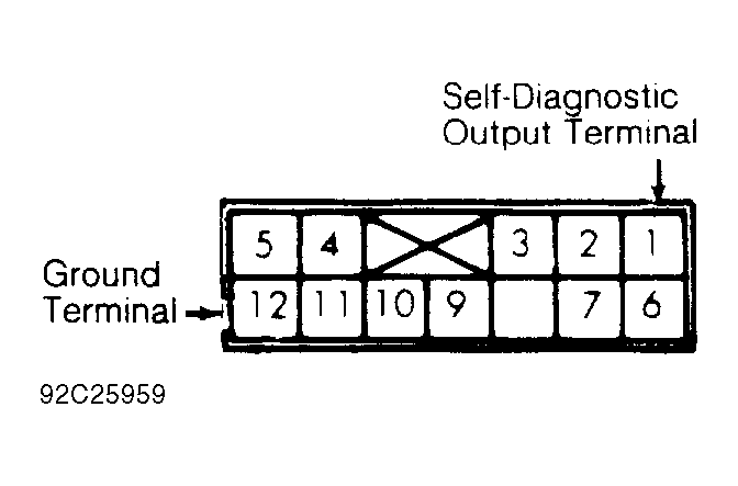
. Turn ignition switch to OFF position. Locate Data Link Connector (DLC), next to fuse block. Connect Diagnostic Harness (MB99159
) between DLC self-diagnostic output terminal and chassis ground. See Fig 1
.
- Turn ignition switch to ON position. Disclosure of ECM memory will begin. If 2 or more systems are non-functional, they are indicated by order of increasing code number. Indication is made by MIL flashes. A constant repetition of short flashes indicates system is normal.
- If system is abnormal, signals will appear on MIL as long and short flashes. Long flashes represent tens; short flashes represent ones. For example, 4 long flashes and 3 short flashes indicate Code 43. After recording trouble code(s), perform necessary repair(s) to indicated circuit(s). See TROUBLE CODES
.
 Courtesy of MITSUBISHI MOTOR SALES OF AMERICA.