Power & Ground Circuits (Quest)
- Start engine. If engine starts, turn engine off and go to step 6. If engine does not start, go to next step.
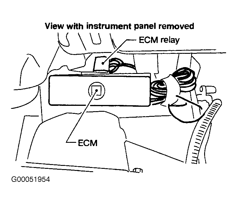
- Turn ignition off, and then on. Backprobing at ECM, measure voltage between ground and ECM terminal No. 24 (Blue/Yellow wire). See Figure and Fig 1
. If battery voltage does not exist, go to next step. If battery voltage exists, go to step 4.
- Check following:
- Check for poor, loose, corroded or damaged terminal connections in in-line harness connectors M42 and F104. See WIRING DIAGRAMS
article.
- Check fuse block fuse No. 4 (10-amp).
- Check for open or short in circuits between ECM and fuse.
If problem is found, repair as necessary. After repair, retest system.
- Turn ignition off. Disconnect ECM 124-pin harness connector. For ECM location, see Fig 1. Check continuity between ground and ECM harness connector terminals No. 10, 19, 116 and 124 (Black wires) and No. 25 and 32 (Black/Red wires). Continuity should exist. See Figure. Also, check harness for short to voltage. If problem is found, leave harness connector disconnected and go to next step. If no problem is found, go to step 15.
- Check following:
- Check for poor, loose, corroded or damaged terminal connections in in-line harness connectors F12 and F201. See WIRING DIAGRAMS
article.
- Check for open or short in circuits between ECM and engine ground.
If problem is found, repair as necessary. After repair, retest system. If no problem is found, connect ECM harness connector and go to next step.
- Turn ignition off. Backprobing at ECM, measure voltage between ground and ECM terminal No. 80 (Yellow wire). See Figure. If battery voltage does not exist, go to next step. If battery voltage exists, go to step 8.
- Check following:
- Check for poor, loose, corroded or damaged terminal connections in in-line harness connectors E53 and F2. See WIRING DIAGRAMS
article.
- Check fuse block fuse No. 4 (10-amp).
- Check for open or short in circuits between ECM and fuse.
If problem is found, repair as necessary. After repair, retest system.
- Turn ignition on, and then off. Backprobing at ECM, measure voltage between ground and ECM terminals No. 67, 72 and 117 (Black/White wires). Battery voltage should exist at each terminal for a few seconds after turning ignition off, then drop to about zero volts. If voltage is as specified, go to step 14. If battery voltage does not exist, go to next step. If battery voltage exists for more than a few seconds, go to step 13.
- Disconnect ECM relay. For ECM relay location, see Fig 1. Measure voltage between ground and ECM relay harness connector terminals No. 2 and 3 (Red wires). See Figure. If battery voltage does not exist, go to next step. If battery voltage exists, leave relay disconnected and go to step 11.
- Check following:
- Check for poor, loose, corroded or damaged terminal connections in in-line harness connectors E53 and F2. See WIRING DIAGRAMS
article.
- Check fuse block fuse No. 4 (10-amp).
- Check for open or short in circuits between ECM and battery.
If problem is found, repair as necessary. After repair, retest system.
- Turn ignition off. Disconnect ECM 124-pin harness connector. For ECM location, see Fig 1. Check continuity in White/Green wire between ECM harness connector terminal No. 4 and ECM relay harness connector terminal No. 1. See Figure and Figure
. Continuity should exist. Also, check circuit for short to ground and short to voltage. If no problem is found, leave harness connector disconnected and go to next step. If problem is found, repair as necessary. After repair, go to next step.
- Check continuity individually between ECM relay harness connector terminal No. 5 and ECM harness connector terminals No. 67, 72 and 117 (Black/White wires). Continuity should exist. Also, check circuit for short to ground or short to voltage. If no problem is found, leave relay and harness connector disconnected and go to next step. If problem is found, repair as necessary. After repair, retest system.
- Working with ECM relay, apply battery voltage and ground to terminals No. 1 and 2. See Figure. When battery voltage is applied, continuity should exist between terminals No. 3 and 5. When battery voltage is removed, continuity should not exist. Replace relay, if test values are not as specified.
- Turn ignition off. Disconnect ECM 124-pin harness connector. For ECM location, see Fig 1. Check continuity between ground and ECM harness connector terminals No. 10, 19, 116 and 124 (Black wires). Also, check continuity between ground and ECM harness connector terminals No. 25 and 32 (Black/Red wires). Continuity should exist. See Figure. Also, check harness for short to voltage. If problem is found, repair as necessary. After repair, retest system. If no problem is found, go to next step.
- No problem is indicated at this time. Problem may be intermittent. See INTERMITTENTS
in TROUBLE SHOOTING - NO CODES article.
 Courtesy of NISSAN MOTOR CO., U.S.A.