Vehicle Speed Sensor (VSS)
- With ignition on, backprobe VSS connector and ensure 12 volts are present at Red/White/Black wire (circuit No. 439). See Fig 1
. Ensure continuity exists between Black/White wire (ground circuit No. 450) and chassis ground.
- Using a DVOM, monitor voltage on Brown wire (circuit No. 437) while turning drive wheels. As Hall switch pulses circuit to ground, voltage should be pulled down. If voltage does not pull down, replace VSS.
- If a Scan tester is used to diagnose this component, see Code 24 diagnostic flow chart in G - TESTS W/ CODES article.
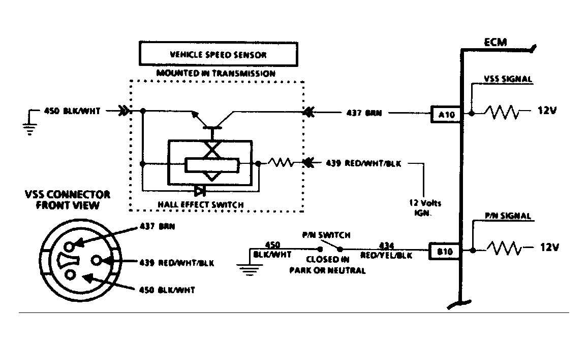 Courtesy of GENERAL MOTORS CORP.