Test E: Retained Accessory Power Inoperative
- If retained accessory power diagnostic system check has been performed, go to next step. If retained accessory power diagnostic system check has not been performed, go to RETAINED ACCESSORY POWER DIAGNOSTIC SYSTEM CHECK under SELF-DIAGNOSTIC SYSTEMS.
- Close all doors. Turn ignition switch from RUN to OFF positions. If Retained Accessory Power (RAP) functions operate normally, go to next step. If RAP functions operate normally, RAP concern may be intermittent. For aid in diagnosing intermittents, see PROBLEM DIAGNOSIS under INTERMITTENTS.
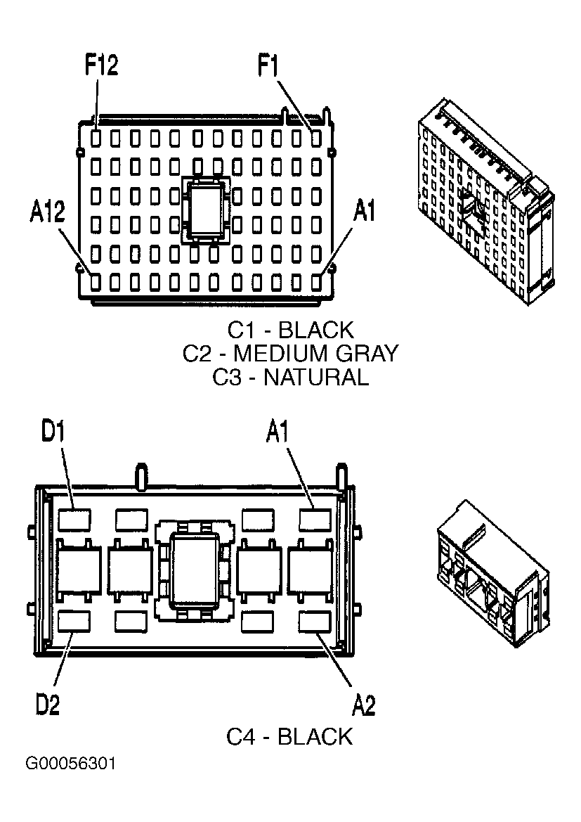
- Turn ignition switch to LOCK position. Remove RAP relay from Center Console (CC) fuse block. CC fuse block is located behind right console access panel, inside of console. Connect a test light between RAP relay ground and control circuits (circuit Nos. 150 & 707). See Figure. Turn ignition switch from RUN to OFF positions. If test light does not illuminate, go to next step. If test light illuminates, go to step 5.
- Check for open in RAP relay ground circuit (circuit No. 150). See Figure. Ground point is located on under right side of instrument panel, on cross beam behind glove box. Check for open in RAP relay control circuit (circuit No. 707). If problem is found, repair as necessary and go to step 11. If no problem is found, go to step 7.
- Connect test light between RAP relay ground and supply voltage circuits (circuit Nos. 42 & 150). See Figure. If test light does not illuminate, go to next step. If test light illuminates, go to step 8.
- Repair open in Red wire between underhood fuse junction block harness connector C4 terminal A2 and RAP relay socket connector No. 42. See Figure and Fig 1
. After repairs are made, go to step 11.
- Check for poor, loose or corroded connections at BCM harness connectors. If no problem is found, go to step 10. If problem is found, repair as necessary and go to step 11.
- Check for open or short to ground in RAP relay output circuit between CC fuse block harness connector C2 terminals D11, E11 or F11 and RAP relay socket connector No. 75. See Figure and Figure
. If no problem is found, go to next step. If problem is found, repair as necessary and go to step 11.
- Replace RAP relay. After repairs are made, go to step 11.
- Replace BCM. See BODY CONTROL MODULE under REMOVAL & INSTALLATION. After repair are made, go to next step.
- Operate RAP system to verify repair. If no problem is found, testing is complete. If problem is found, go to step 2.
 Courtesy of GENERAL MOTORS CORP.