DTC U1016: Lost Communications With Engine Controls System
- Perform VEHICLE ON-BOARD DIAGNOSTIC SYSTEM CHECK under SELF-DIAGNOSTIC SYSTEM. If body control module diagnostic system check has been performed, go to next step.
- Observe scan tool display for DTC U1016. If scan tool displays LAST TEST FAILED for DTC U1016, go to next step. If scan tool does not display LAST TEST FAILED for DTC U1016, problem is intermittent. Check for poor connection at Powertrain Control Module (PCM). Check for open or poor connection in serial data line (Purple wire). See DATA LINK CONNECTORS article in WIRING DIAGRAMS. Repair as necessary and retest operation.
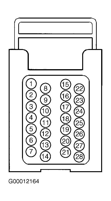
- Turn ignition off. Gain access to Powertrain Control Module (PCM), located in left rear corner of engine compartment. Disconnect PCM. Connect test light between ground and Black 28-pin PCM connector terminals No. 1 and No. 6 (Orange wires). See Fig 1. See POWER DISTRIBUTION article in WIRING DIAGRAMS. If test light illuminates, go to step 5. If test light does not illuminate, go to next step.
- Repair open in Orange wire between Black 28-pin PCM connector terminals No. 1 and/or No. 6 and PCM B fuse (10-amp), located in underhood fuse block. See COMPONENT LOCATIONS . Retest operation.
- Turn ignition on. Connect test light between ground and Black 28-pin PCM connector terminal No. 23 (Pink wire). If test light illuminates, go to next step. If test light does not illuminate, repair open in Pink wire between Black 28-pin PCM connector terminal No. 23 and PCM 1 fuse (10-amp), located in underhood fuse block. Retest operation.
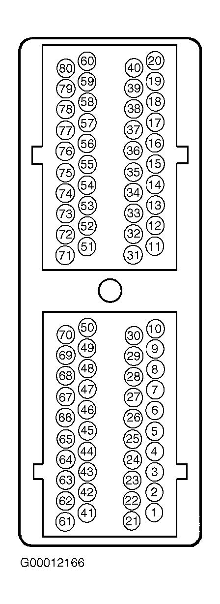
- On models equipped with manual transmission, connect test light between battery voltage and Black 80-pin PCM connector terminal No. 56 (Tan/White wire). See Fig 2. On models equipped with automatic transmission, connect test light between battery voltage and Black 80-pin PCM connector terminals No. 55, 76 and 77 (Tan/White wires). On all models, if test light illuminates, go to next step. If test light does not illuminate, repair open in appropriate Tan/White wire between PCM and ground. See GROUND DISTRIBUTION article in WIRING DIAGRAMS.
- Connect test light between battery voltage and PCM case. If test light illuminates, go to next step. If test light does not illuminate, check for open in PCM braided ground wire. Repair as necessary and retest operation.
- Check for poor connections to PCM. Repair as necessary. If PCM connections are okay, replace PCM. See appropriate REMOVAL, OVERHAUL & INSTALLATION article in ENGINE PERFORMANCE.
 Courtesy of GENERAL MOTORS CORP.
 Courtesy of GENERAL MOTORS CORP.