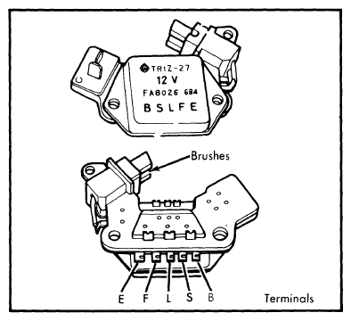
Integrated Circuit (Ic) Regulator: Testing
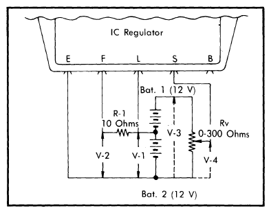
- Remove brush assembly and with suitable tester, connect wiring as shown in Fig 2. If V-1 voltage is not within 10-13 volts, charge or replace battery as necessary. Disconnect lead at terminal "S" and check voltage between terminals "F" and "E". If less than 2.0 volts, regulator is functioning properly.
 Courtesy of NOT AVAILABLE
- Measure total voltage (V-3) of batteries 1 and 2. If not within 20-26 volts, recharge or replace. Gradually decrease variable resistance (Rv) from 300 ohms and check voltage (V-2) between terminals "E" and "F". At some point, V-2 should increase to equal V-1 measured in step 1). If no V-2 variation occurs as described, regulator is defective.
- Measure voltage (V-4) between center tap of variable resistor (Rv) and terminal "E". With resistance set as in previous step, voltage should be 14.7 ±.5 volts at 68°F (20°C). At extremely high case temperatures, voltage may be 1 volt lower, while at extremely cold temperatures, voltage may be 1 volt higher.
- Remove test lead from terminal "S" and connect to terminal "B". Repeat steps 2) and 3) and check for voltage (V-4) 0.5 - 2.0 volts higher than in step 3). If testing specifications are not met, it will be necessary to replace the IC regulator/brush assembly.
 Courtesy of NOT AVAILABLE