Fuel Pump Circuit Tests
- Check Fuel Pump Operation
Connect test mode connector and turn ignition on. Ensure fuel pump operates for 2 seconds after turning ignition on. If fuel pump operates for 2 seconds, check fuel injector circuit. See FUEL INJECTOR CIRCUIT TESTS . If fuel pump does not operate, go to next step.
- Check Fuel Pump Ground Circuit
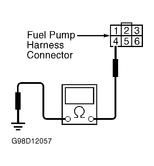
Turn ignition off. Remove fuel pump access hole cover in right rear corner of trunk (luggage compartment on wagons) and disconnect connector from fuel pump. Check resistance between ground and fuel pump harness 6-pin connector terminal No. 4. See Fig 1. If resistance is less than 5 ohms, go to next step. If resistance is more than 5 ohms, repair open in fuel pump ground circuit or repair poor contact in connectors. See appropriate wiring diagram in WIRING DIAGRAMS
article.
 Courtesy of SUBARU OF AMERICA, INC.
- Check Fuel Pump Power Supply
Turn ignition on. Check voltage between ground and fuel pump 6-pin connector terminal No. 1. See Fig 1. Voltage should be more than 10 volts. If voltage is more than 10 volts, replace fuel pump. If voltage is less than 10 volts, go to next step.
- Check Harness Between Fuel Pump & Fuel Pump Relay
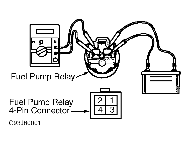
Turn ignition off. Measure resistance between harness 6-pin connector terminal No. 1 and fuel pump relay 4-pin connector terminal No. 4. See Fig 1 and Fig 2
. Resistance should be less than one ohm. If resistance is one ohm or more, repair open in harness between fuel pump and fuel pump relay connector. See appropriate wiring diagram in WIRING DIAGRAMS
article. If resistance is less than one ohm, check resistance between fuel pump 6-pin connector terminal No. 1 and ground. Resistance should be more than one megohm. If resistance is less than one megohm, repair short in harness between fuel pump and fuel pump relay.
- Check Fuel Pump Relay
Disconnect connectors from fuel pump relay and main relay. Remove fuel pump relay and main relay with bracket. Connect battery voltage and ground to fuel pump relay terminals No. 1 and 3. Ensure there is less than 10 ohms resistance between terminals No. 2 and 4. See Fig 2. If resistance is less than 10 ohms, go to next step. If resistance is greater than 10 ohms, replace fuel pump relay. See appropriate wiring diagram in WIRING DIAGRAMS
article.
- Check Harness Between ECM & Fuel Pump Relay
Disconnect connectors from ECM. Measure resistance of harness between ECM connector B134 (35-pin connector) terminal No. 16 and fuel pump relay 4-pin connector terminal No. 3. See Figure. Resistance should be less than one ohm. If resistance is less than one ohm, check for poor contact in ECM connector. If resistance is more than one ohm, repair open circuit in harness between ECM and fuel pump relay. See appropriate wiring diagram in WIRING DIAGRAMS
article.
 Courtesy of SUBARU OF AMERICA, INC.