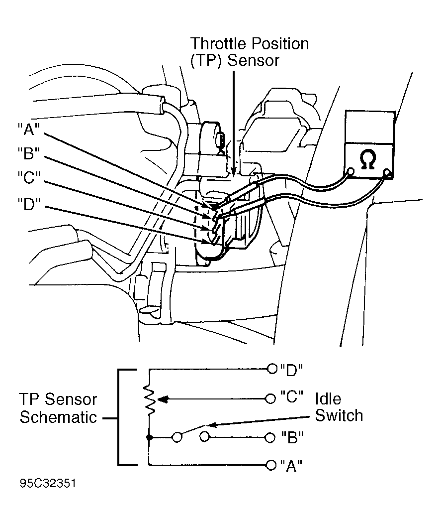
Throttle Position (TP) Sensor
- Disconnect negative battery cable and TP sensor connector. See Fig 1
. Using an ohmmeter, check resistance between indicated terminals. See the THROTTLE POSITION (TP) SENSOR RESISTANCE
table.
- If resistance is not as specified, adjust TP sensor. See appropriate ADJUSTMENTS
article. If resistance is not as specified after adjustment, replace TP sensor. For further diagnostic procedures, see appropriate BASIC TESTING
article. Since many computer-controlled and monitored components set a Diagnostic Trouble Code (DTC) if they malfunction, also perform procedures in appropriate TESTS W/CODES
article.
THROTTLE POSITION (TP) SENSOR RESISTANCE
| Application |
Ohms |
| Between Terminals "A" & "C" |
100-20,000 |
| Between Terminals "A" & "D" |
2870-5330 |
 Courtesy of GENERAL MOTORS CORP.