Electronic Control System Description
ELECTRONIC CONTROL SYSTEM DESCRIPTIONThe electronic control system consists of various sensors which detect the state of engine and driving conditions, ECM which controls various devices according to the signals from the sensors and various controlled devices.
Functionally, it is divided into the following sub systems:
- Fuel injection control system
- Ignition control system
- Idle air control system
- Fuel pump control system
- Radiator fan control system
- Evaporative emission control system
- EGR system
- Heated oxygen sensor heater control system
- A/C control system
Engine And Emission Control System Flow Diagram:
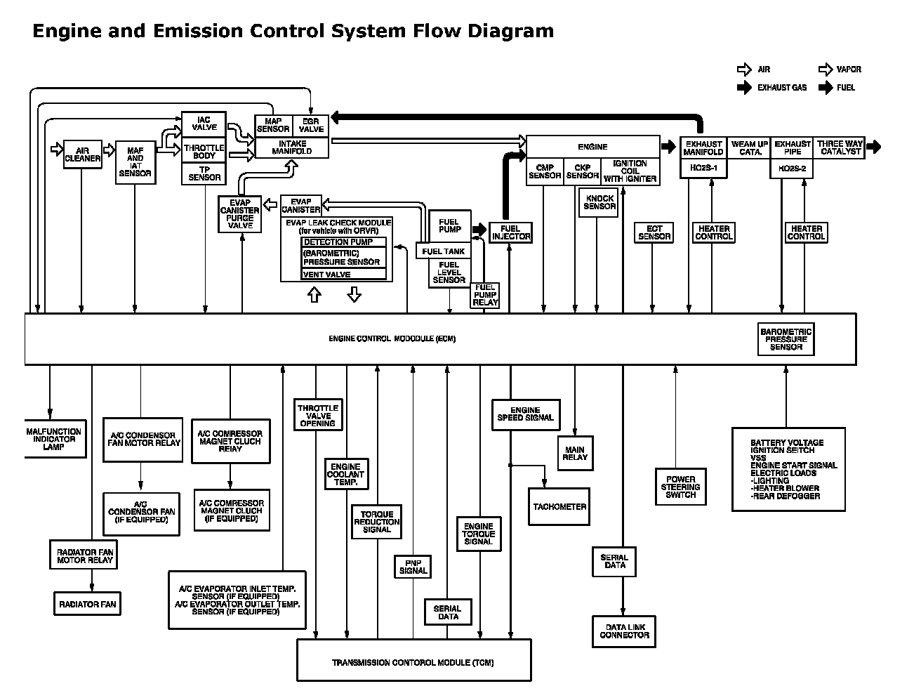
Engine and Emission Control System Flow Diagram
ECM Input / Output Circuit Diagram:
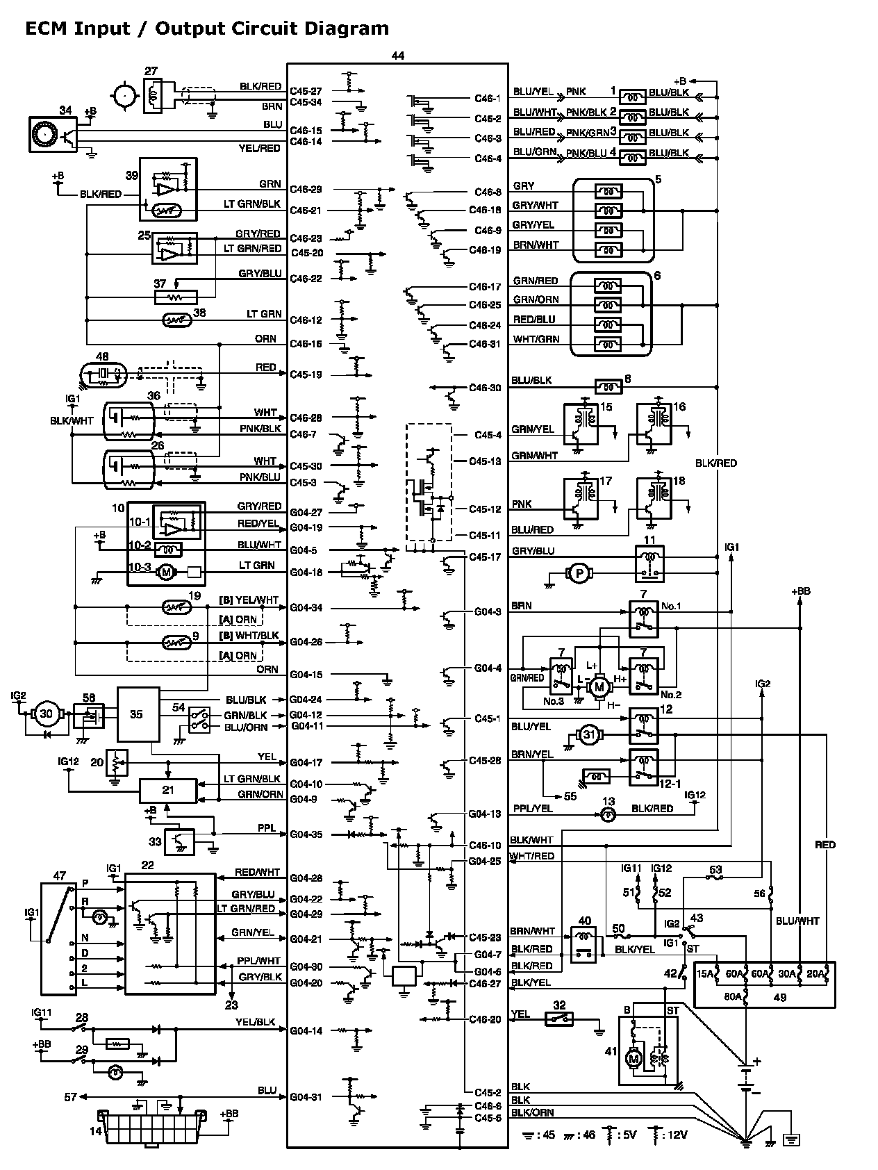
ECM Input / Output Circuit Diagram
Term. G04-1 - G04-35:
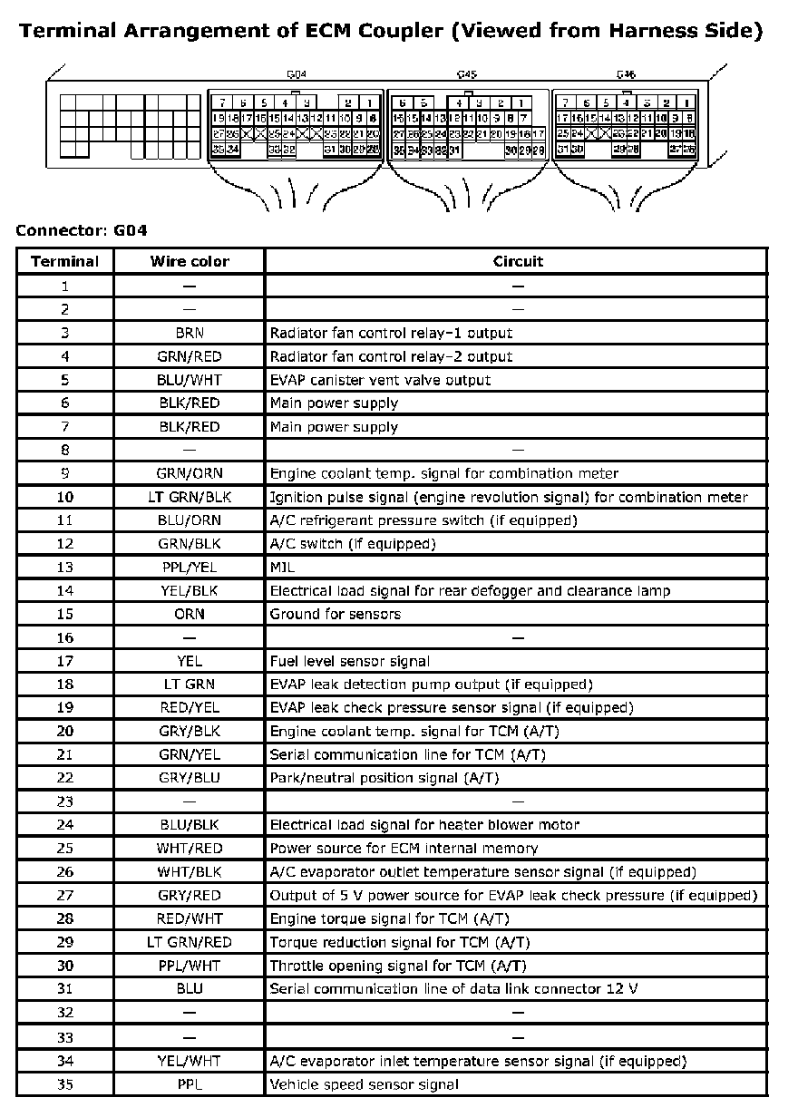
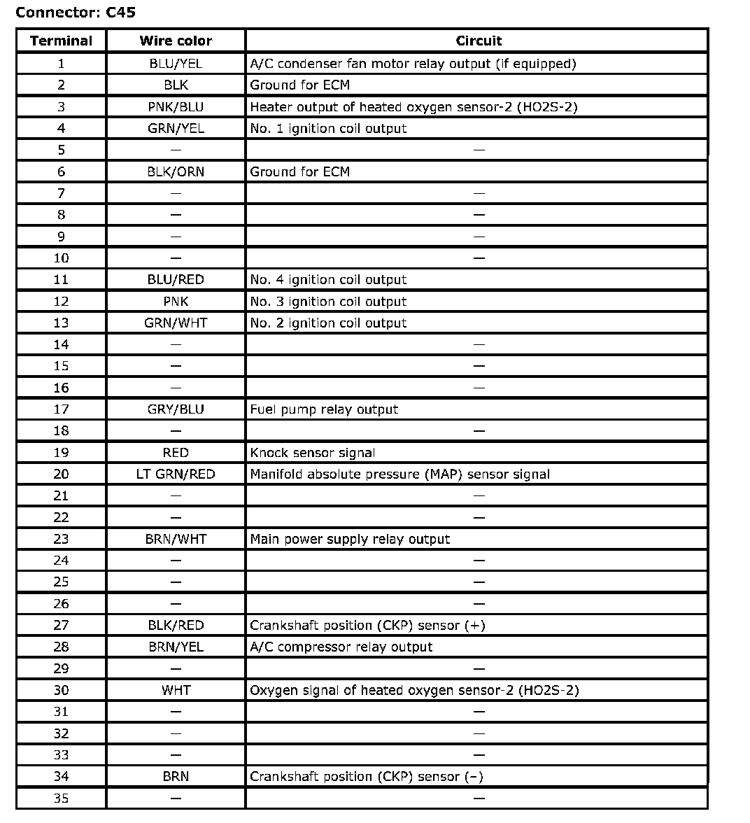
Term. C45-1 - C45-35:
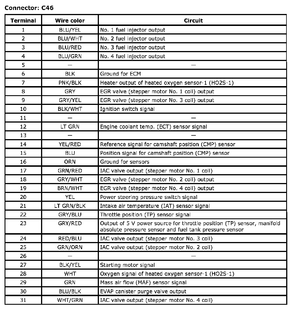
Term. C46-1 - C46-31:
Terminal Arrangement of ECM Coupler (Viewed from Harness Side)
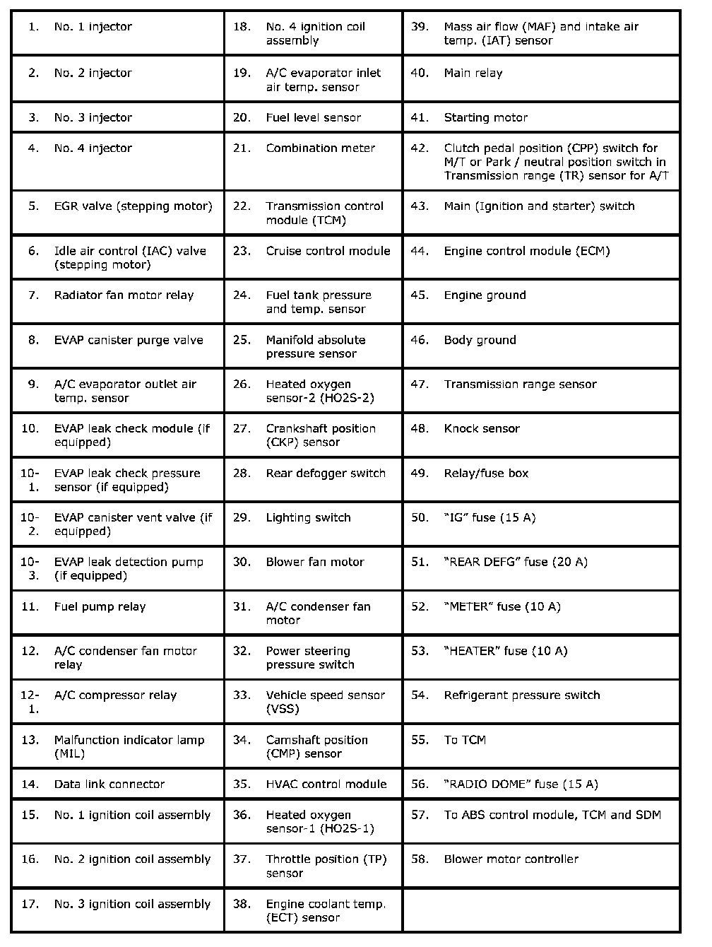
Engine And Emission Control Input / Output Table:
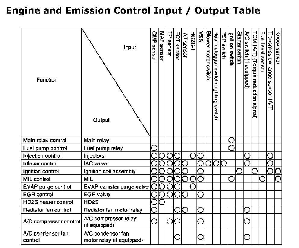
Engine and Emission Control Input/Output Table