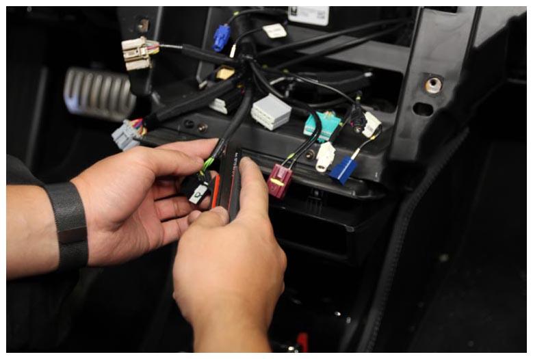
- Locate the black connector X428, and then unwrap the protective loom up to the junction bundle on the electrical harness.
CAUTION:
Do not cut the harness.
 Courtesy of TESLA, INC. Courtesy of TESLA, INC.
|
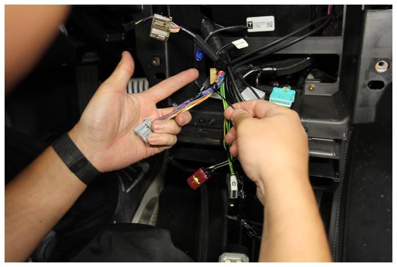
- Locate the gray connector X429, and then unwrap the protective loom up to the junction bundle on the electrical harness.
 Courtesy of TESLA, INC. Courtesy of TESLA, INC.
|
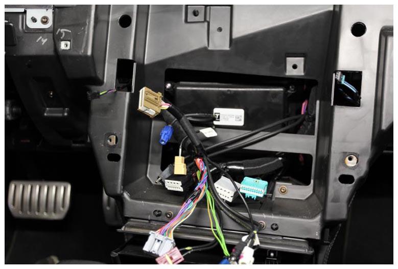
- Locate the brown connector X430, and then unwrap the protective loom up to the junction bundle on the electrical harness.
 Courtesy of TESLA, INC. Courtesy of TESLA, INC.
|
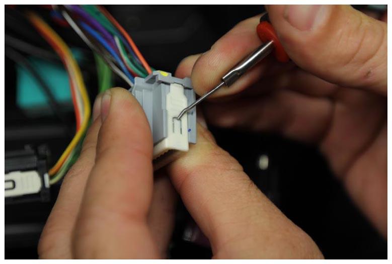
- Release the terminal locks for the black connector X428, gray connector X429, and brown connector X430 with a suitable tool from the Pin Drag Kit. Push the tabs on both sides to release the white terminal lock, and then fully remove the terminal lock from each connector.
NOTE:
Gray Connector X429, Black Connector X428 Similar
 Courtesy of TESLA, INC. Courtesy of TESLA, INC.
|
NOTE:
Brown Connector X430, Black Connector X428 Similar
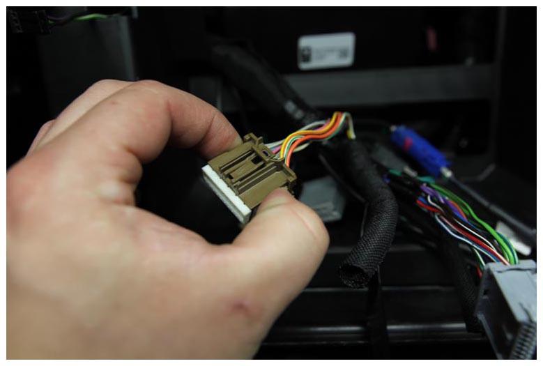 Courtesy of TESLA, INC. Courtesy of TESLA, INC.
|
- Insert the terminal release tool from the Pin Drag Kit into the release hole for terminal 2 of gray connector X429. Release the terminal and remove the wire from the back of the connector.
NOTE:
The wire is colored either Yellow/Orange or Yellow/Light Green.
NOTE:
Remove terminal 2 from grey connector X429
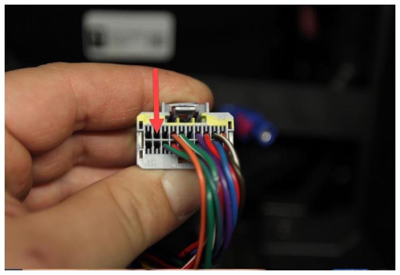 Courtesy of TESLA, INC. Courtesy of TESLA, INC.
|
- Insert the wire just removed into cavity 3 of brown connector X430 until it is locked into position.
NOTE:
Insert into cavity 3 of brown connector X430
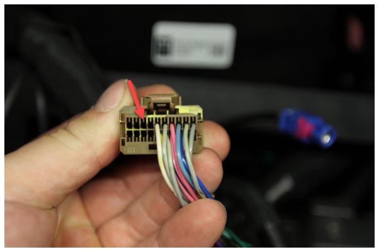 Courtesy of TESLA, INC. Courtesy of TESLA, INC.
|
- Insert the terminal release tool from the Pin Drag Kit into the release hole for terminal 11 of gray connector X429. Release the terminal and remove the wire from the back of the connector.
NOTE:
The wire is colored either White/Dark Green or White/Dark Blue
NOTE:
Remove terminal 11 from grey connector X429
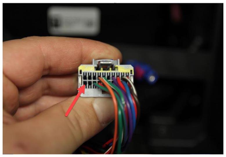 Courtesy of TESLA, INC. Courtesy of TESLA, INC.
|
- Insert the wire just removed into cavity 13 of brown connector X430 until it is locked into position.
NOTE:
Insert into cavity 13 of brown connector X430
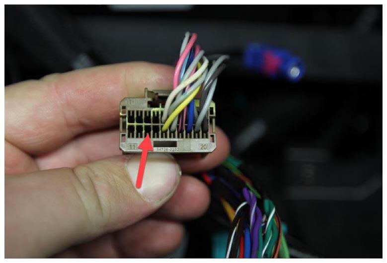 Courtesy of TESLA, INC. Courtesy of TESLA, INC.
|
- Insert the terminal release tool from the Pin Drag Kit into the release hole for terminal 12 of gray connector X429. Release the terminal and remove the wire from the back of the connector.
NOTE:
The wire is colored Orange.
NOTE:
Remove terminal 12 from grey connector X429
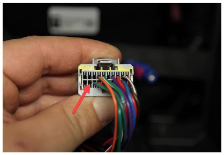 Courtesy of TESLA, INC. Courtesy of TESLA, INC.
|
- Insert the wire just removed into cavity 12 of brown connector X430 until it is locked into position.
NOTE:
Insert into cavity 12 of brown connector X430
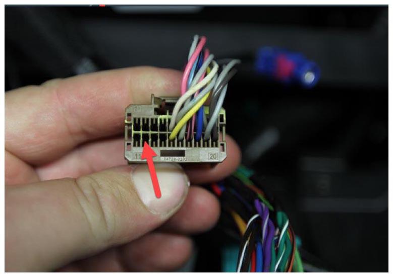 Courtesy of TESLA, INC. Courtesy of TESLA, INC.
|
- Insert the terminal release tool from the Pin Drag Kit into the release hole for terminal 9 of black connector X428. Release the terminal and remove the wire from the back of the connector.
NOTE:
The wire is colored Light Green/Dark Blue, or just Light Green.
NOTE:
Remove terminal 9 from black connector X428
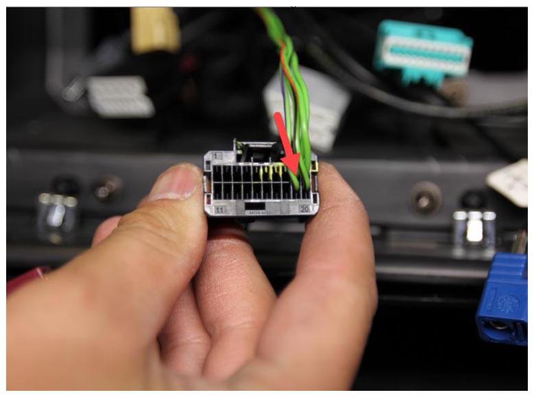 Courtesy of TESLA, INC. Courtesy of TESLA, INC.
|
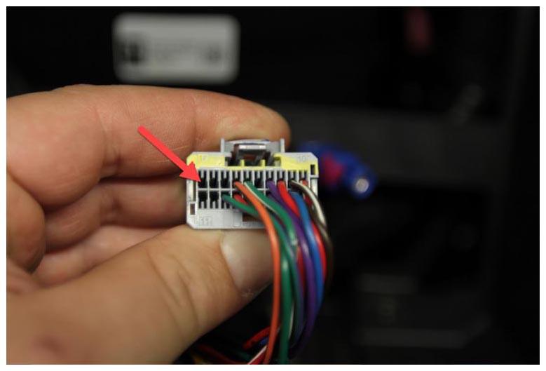
- Insert the wire just removed into cavity 1 of gray connector X429 until it is locked into position.
NOTE:
Insert into cavity 1 of gray connector X429
 Courtesy of TESLA, INC. Courtesy of TESLA, INC.
|
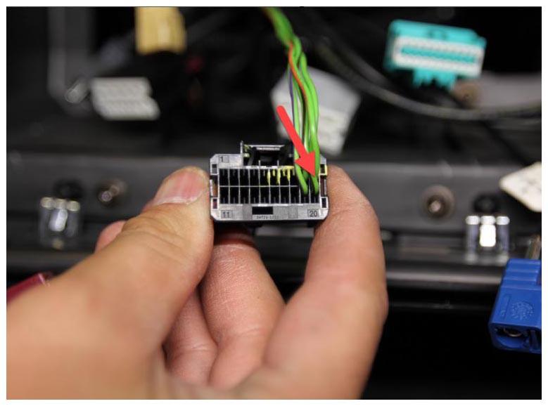
- Insert the terminal release tool from the Pin Drag Kit into the release hole for terminal 10 of black connector X428. Release the terminal and remove the wire from the back of the connector.
NOTE:
The wire is colored Light Green/Orange.
NOTE:
Remove terminal 10 from black connector X428
 Courtesy of TESLA, INC. Courtesy of TESLA, INC.
|
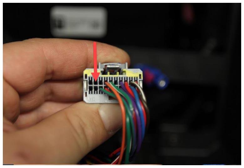
- Insert the wire just removed into cavity 2 of gray connector X429 until it is locked into position.
NOTE:
Insert into cavity 2 of gray connector X429
 Courtesy of TESLA, INC. Courtesy of TESLA, INC.
|
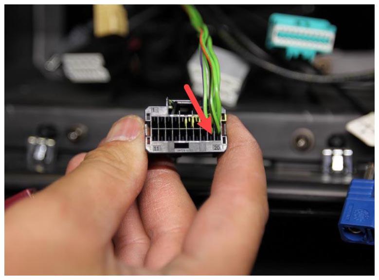
- Insert the terminal release tool from the Pin Drag Kit into the release hole for terminal 19 of black connector X428. Release the terminal and remove the wire from the back of the connector.
NOTE:
The wire is colored Light Green/Purple.
NOTE:
Remove terminal 19 from black connector X428
 Courtesy of TESLA, INC. Courtesy of TESLA, INC.
|
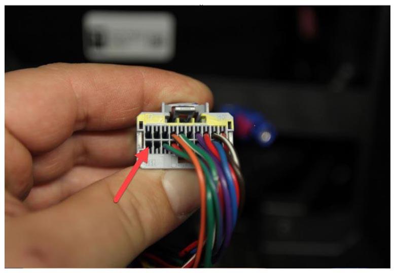
- Insert the wire just removed into cavity 11 of gray connector X429 until it is locked into position.
NOTE:
Insert into cavity 11 of gray connector X429
 Courtesy of TESLA, INC. Courtesy of TESLA, INC.
|
- Vehicles manufactured from September 17, 2015 to April 10, 2016 might have only 3 wires in black connector X428. If there is a wire in terminal 20 of black connector X428, perform the next step. If not, skip to step 20.
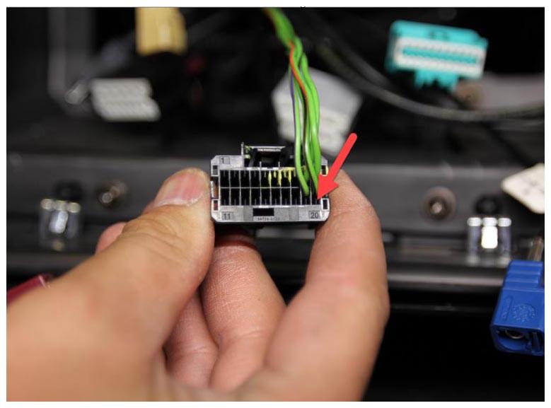
- Insert the terminal release tool from the Pin Drag Kit into the release hole for terminal 20 of black connector X428. Release the terminal and remove the wire from the back of the connector.
NOTE:
The wire is colored Light Green/Brown.
NOTE:
Remove terminal 20 from black connector X428
 Courtesy of TESLA, INC. Courtesy of TESLA, INC.
|
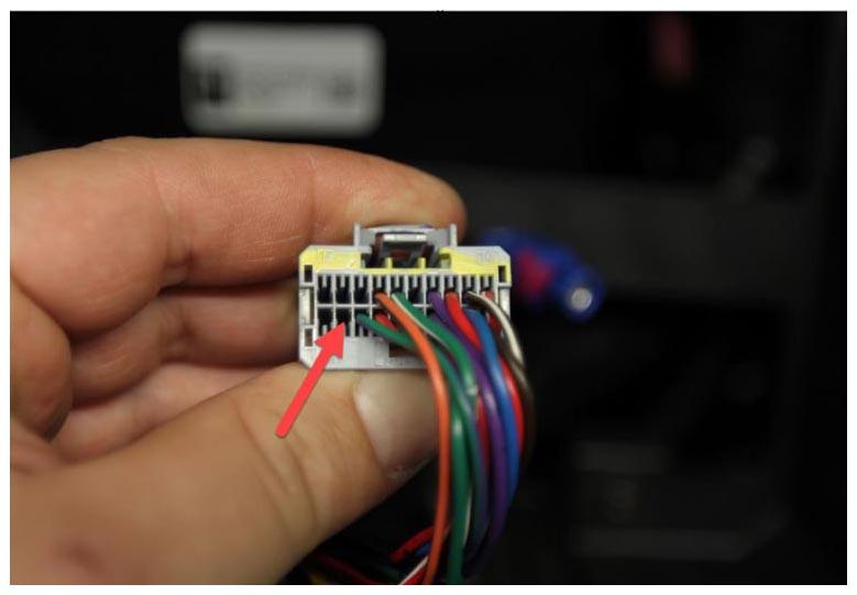
- Insert the wire just removed into cavity 12 of gray connector X429 until it is locked into position.
NOTE:
Insert into cavity 12 of gray connector X429
 Courtesy of TESLA, INC. Courtesy of TESLA, INC.
|
- Install the terminal locks for the gray connector X429 and brown connector X430.
- Reinstall the protective loom onto gray connector X429, and then apply yellow wire harness tape to secure the wires.
NOTE:
Use yellow wire harness tape to indicate that the retrofit has been performed.
- Reinstall the protective loom onto the brown connector X430, and then apply yellow wire harness tape to secure the wires.
NOTE:
Use yellow wire harness tape to indicate that the retrofit has been performed.
- Clean the top surface of the IP carrier with an isopropyl alcohol (IPA) wipe.
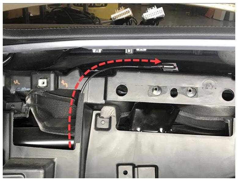
- Install a new Bluetooth antenna on top of the IP carrier and route the wire through the LH inner vent opening into the wire harness access area.
NOTE:
Use wire harness tape to attach the wire harness to the IP carrier.
 Courtesy of TESLA, INC. Courtesy of TESLA, INC.
|
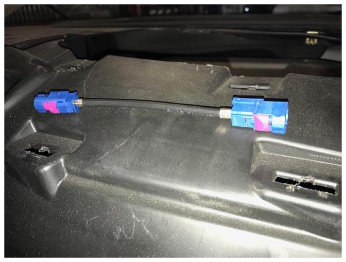
- Install the reverse camera cable extension on the MCU.
NOTE:
Cover the connector points with wire harness tape to prevent noise, vibration, and harshness (NVH) issues.
NOTE:
The reverse camera cable extension is supplied in the MCU service kit.
 Courtesy of TESLA, INC. Courtesy of TESLA, INC.
|
- Install the touchscreen surround trim onto the new MCU Trim - Touchscreen Surround (Remove And Replace)
.
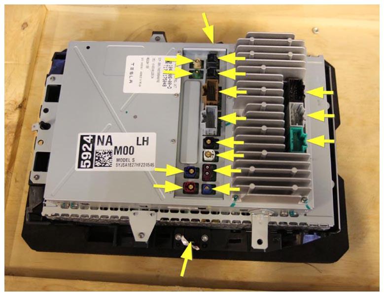
- Position the new MCU into the vehicle.
- Connect all harness connectors.
 Courtesy of TESLA, INC. Courtesy of TESLA, INC.
|
- Install the MCU into the IP carrier Media Control Unit (Remove And Install)
.
NOTE:
Do not install the MCU mounting screws that attach the MCU to the IP carrier.
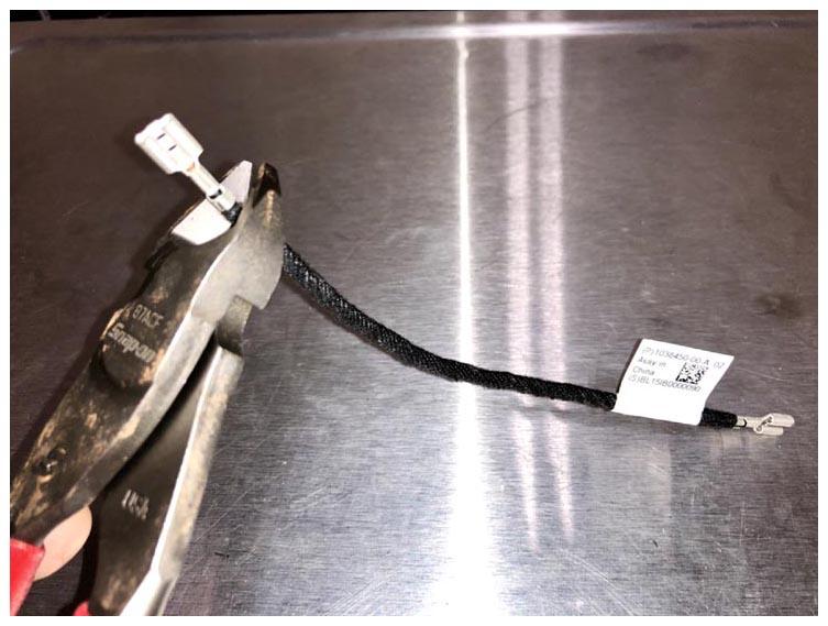
- If the MCU does not have a grounding tab, follow these steps:
- Cut the female spade off the IP trim ground strap.
 Courtesy of TESLA, INC. Courtesy of TESLA, INC.
|
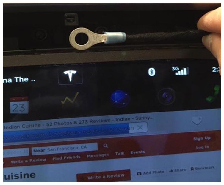
- Strip the insulation off the end of the ground strap, and then add a ring terminal.
 Courtesy of TESLA, INC. Courtesy of TESLA, INC.
|
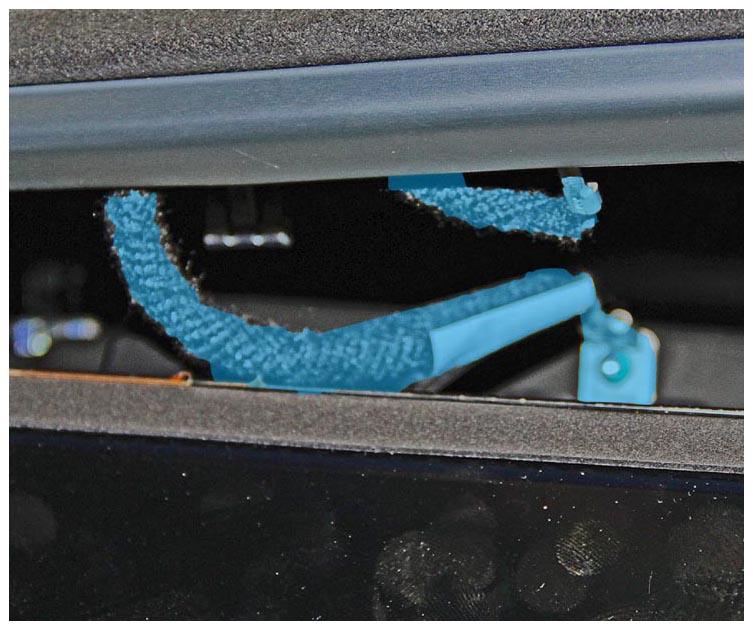
- Install the ground strap to the IP top pad.
CAUTION:
Failure to ground to the chassis of the vehicle can result in damage to the connectivity board.
 Courtesy of TESLA, INC. Courtesy of TESLA, INC.
|
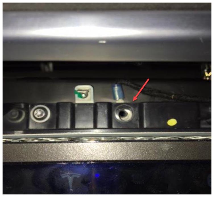
- Insert the ring terminal between the plastic and metal of the MCU mounting point.
 Courtesy of TESLA, INC. Courtesy of TESLA, INC.
|