Valve Clearance: PASEO
- Remove valve cover(s) and gasket(s). Rotate crankshaft so timing mark on crankshaft pulley aligns with "0" mark on front cover and cylinder No. 1 (front cylinder at timing belt or timing chain end) is at TDC on compression stroke.
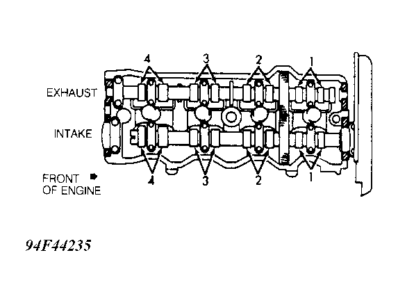
- Ensure valves on cylinder No. 1 are closed. If valves are not closed, rotate crankshaft 360 degrees (one full revolution). With cylinder No. 1 at TDC, check valve clearance on specified valves. See the VALVE CLEARANCE ADJUSTMENT SEQUENCE table. See Fig 1.
 Courtesy of © TOYOTA, LICENSE AGREEMENT TMS1002
- Using feeler gauge, measure and record valve clearance between valve lifter and camshaft. Ensure valve clearance is within specification. See VALVE CLEARANCE SPECIFICATIONS table.
- To check remaining valves, rotate crankshaft 360 degrees (one full revolution) until cylinder No. 4 is at TDC on compression stroke. Measure valve clearance on specified valves. See appropriate VALVE CLEARANCE ADJUSTMENT SEQUENCE table.
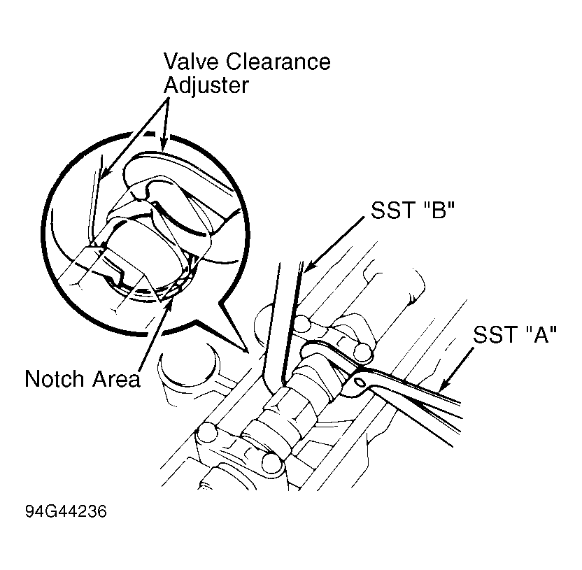
- If valve clearance requires adjustment, rotate crankshaft so camshaft lobe on valve to be adjusted is facing upward, away from valve lifter. Rotate valve lifter so notch on valve lifter is toward spark plug.
- Valve Clearance Adjuster (SST 09248-55040) is used for adjusting valve clearance. Press valve lifter downward using SST "A" of valve clearance adjuster. See Fig 2. Install SST "B" between camshaft and valve lifter. Remove SST "A". Shim thickness can also be determined by using the following formula: N = T + A.
- N = Thickness of adjuster shim required.
- T = Thickness of adjuster shim removed.
- A = Measured clearance minus valve clearance specification.
- Using small screwdriver and magnet, remove adjusting shim. Using micrometer, measure thickness of adjusting shim removed. Using measured clearance and adjusting shim thickness, determine correct thickness of adjusting shim to be used. See SHIM THICKNESS table. Install adjusting shim. Recheck valve clearance.
NOTE:
Before installing valve cover gasket, apply sealant at camshaft bearing caps-to-cylinder head surfaces where valve cover gasket seals.
- Install valve cover using NEW gasket. On Previa, remove bolt from accessory drive shaft. Reverse removal procedure to install remaining components.
 Courtesy of © TOYOTA, LICENSE AGREEMENT TMS1002
 VALVE CLEARANCE ADJUSTMENT SEQUENCE
| Piston No. On TDC |
Adjust Intake Valves |
Adjust Exhaust Valves |
| 1 |
1 & 2 |
1 & 3 |
| 4 |
3 & 4 |
2 & 4 |
VALVE CLEARANCE SPECIFICATIONS
| Application |
In. (mm) |
| Paseo |
| Exhaust |
.012-.016 (.30-.41) |
| Intake |
.006-.010 (.15-.25) |
| Tercel (Exhaust & Intake) |
.008 (.20) |
SHIM THICKNESS
| Thickness mm (in.) |
Shim No. |
| 2.50 (0.0984) |
1 |
| 2.55 (0.1004) |
2 |
| 2.60 (0.1024) |
3 |
| 2.65 (0.1043) |
4 |
| 2.70 (0.1063) |
5 |
| 2.75 (0.1083) |
6 |
| 2.80 (0.1102) |
7 |
| 2.85 (0.1122) |
8 |
| 2.90 (0.1142) |
9 |
| 2.95 (0.1161) |
10 |
| 3.00 (0.1181) |
11 |
| 3.05 (0.1201) |
12 |
| 3.10 (0.1220) |
13 |
| 3.15 (0.1240) |
14 |
| 3.20 (0.1260) |
15 |
| 3.25 (0.1280) |
16 |
| 3.30 (0.1299) |
17 |