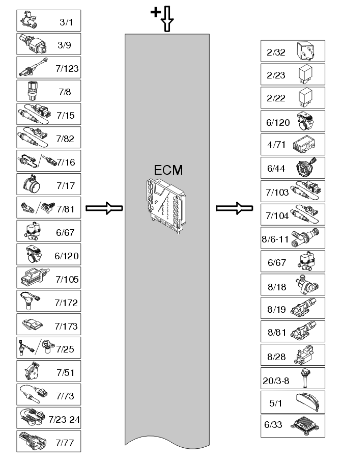
System overview: Signals
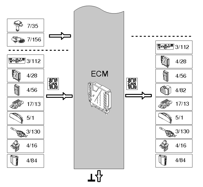
The chart below summarizes the input signals to and output signals from the Engine Control Module (ECM). The signal types are divided into directly connected signals, serial communication and controller area network (CAN) communication. The illustration below displays the same information with the Volvo component designations.
| Input signals |
Output signals |
| Directly connected: |
Directly connected: |
- Ignition switch (3/1)
- Stop lamp switch (3/9)
- Clutch pedal sensor (7/123)
- Air conditioning (A/C) pressure sensor (7/8)
- Front heated oxygen sensor (HO2S) (7/15)
- Rear heated oxygen sensor (HO2S) (7/82)
- Engine coolant temperature (ECT) sensor (7/16)
- Mass air flow (MAF) sensor (7/17)
- Manifold absolute pressure (MAP) sensor, intake (7/81) (certain turbocharged engines only)
- Manifold absolute pressure (MAP) sensor, with integrated intake air temperature (IAT) sensor, intake (7/81) (certain turbocharged engines only)
- Leak diagnostic unit (6/67), (certain markets only)
- Electronic throttle unit (6/120)
- Outside temperature sensor (7/105)
- Camshaft position (CMP) sensor (7/172)
- Camshaft position (CMP) sensor (7/173)
- Engine speed (RPM) sensor (7/25)
- Accelerator pedal (AP) position sensor (7/51)
- Engine coolant level sensor (7/73)
- Knock sensor (KS) (7/23-7/24)
- Manifold absolute pressure (MAP) sensor, intake (7/77) (not turbocharged engines 2003-2004)
- Oil level sensor (7/35) (certain markets and models only)
- Fuel pressure sensor with integrated fuel temperature sensor (7/156) (vehicles with demand controlled fuel pumps only).
|
- Main relay (system relay) (2/32)
- Fuel pump (FP) relay (2/23)
- Air conditioning (A/C) relay (2/22)
- Electronic throttle unit (6/120)
- Engine cooling fan (FC) control module (4/71)
- Engine cooling fan (FC) control module box (6/44) (turbocharger (TC) only and certain markets)
- Front heated oxygen sensor (HO2S), preheating (7/103)
- Rear heated oxygen sensor (HO2S), preheating (7/104)
- Injectors (8/6-8/11)
- Leak diagnostic unit (6/67), (certain markets only)
- Evaporative emission system (EVAP) valve (8/18)
- Camshaft reset valve (CVVT) (8/19) (certain engines only)
- Camshaft reset valve (CVVT) (8/81) (certain engines only)
- Turbocharger (TC) control valve (8/28)
- Ignition coils (20/3-20/8)
- Driver information module (DIM) (5/1), emissions warning lamp
- Fuel pump control module (6/33) (only vehicles with demand controlled fuel pumps)
- Central electronic module (CEM) (4/56).
|
| Via Controller Area Network (CAN) communication: |
Via Controller Area Network (CAN) communication: |
- Transmission Control Module (TCM) (4/28) (only cars with automatic transmissions)
- Brake control module (BCM) (4/16)
- Central electronic module (CEM) (4/56)
- Suspension module (SUM) (4/84) (vehicle with Four-C (Continuously Controlled Chassis Concept) only).
Via central electronic module (CEM) (4/56):
- Climate Control Module (CCM) (3/112)
- Data link connector (DLC) (17/13)
- Driver information module (DIM) (5/1)
- Steering wheel module (SWM) (3/130).
|
- Transmission Control Module (TCM) (4/28) (only cars with automatic transmissions)
- Brake control module (BCM) (4/16)
- Central electronic module (CEM) (4/56)
- Differential electronic module (DEM) (4/82) (AWD only)
- Suspension module (SUM) (4/84) (vehicle with Four-C (Continuously Controlled Chassis Concept) only).
Via central electronic module (CEM) (4/56):
- Climate Control Module (CCM) (3/112)
- Data link connector (DLC) (17/13)
- Driver information module (DIM) (5/1)
- Steering wheel module (SWM) (3/130).
|
 Courtesy of VOLVO CARS OF NORTH AMERICA.
 Courtesy of VOLVO CARS OF NORTH AMERICA.