System Overview: Signals
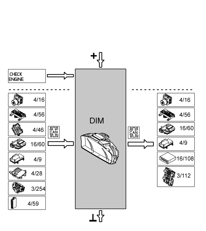
The following table summarizes input and output signals to and from the driver information module (DIM). The signal types are divided into directly connected signals and Controller area network (CAN) communication. The illustration below (Fig 1) displays the same information with the Volvo component designations.
| Input signals |
Output signals |
| Directly connected: |
Directly connected:
(Power supply unless otherwise stated) |
- Malfunction indicator lamp (MIL).
|
- |
| Via Controller Area Network (CAN) communication: |
Via Controller Area Network (CAN) communication: |
- Brake control module (BCM) (4/16)
- Central electronic module (CEM) (4/56)
- Engine control module (ECM) (4/46)
- Phone module (PHM) (16/60)
- Supplemental Restraint System Module (SRS) (4/9)
- Transmission Control Module (TCM) (4/28)
- Steering wheel module (SWM) (3/254).
- Convertible Roof Module (CRM) (4/59) (only applies to C70)
|
- Brake control module (BCM) (4/16)
- Central electronic module (CEM) (4/56)
- Phone module (PHM) (16/60)
- Supplemental Restraint System Module (SRS) (4/9)
- Multimedia module (MMM) (16/108)
- Climate control module (CCM) (3/112).
|
 Courtesy of VOLVO CARS CORPORATION