System Overview: Signals
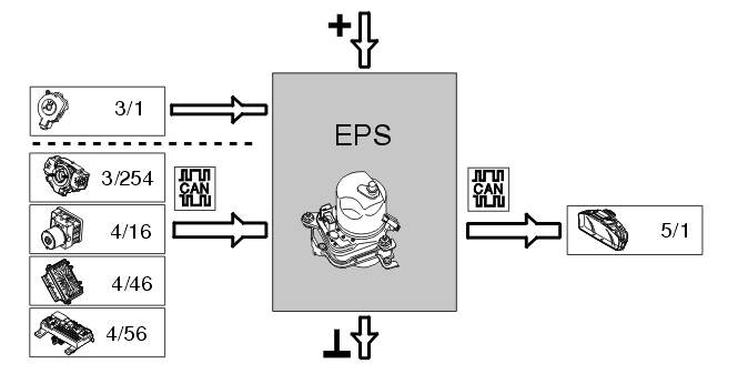
The table below summarizes the input signals to and output signals from the electrical power steering module (EPS).
The signal types are divided into directly connected signals and Controller area network (CAN) communication. The illustration below (Fig 1) displays the same information with the Volvo component designations.
| Input signals |
Output signals |
| Directly connected: |
Directly connected: |
Ignition
(3/1):
- Position II (15-feed) "wakes up" the electrical power steering module (EPS).
|
- |
| Via Controller Area Network (CAN) communication: |
Via Controller Area Network (CAN) communication: |
Steering wheel module (SWM)
(3/254):
- Its function is to provide information about the steering wheel angle speed. This information is used together with the vehicle speed signal from the brake control module (BCM) to calculate the desired value for the pump motor speed.
Brake control module (BCM)
(4/16):
- Actual vehicle speed (calculated from the wheel speed sensors). Used for the speed related steering assistance.
Engine control module (ECM)
(4/46):
- Indicates whether the engine is running or not (engine status/engine speed).
Central electronic module (CEM)
(4/56): |
Driver information module (DIM)
(5/1):
- For certain registered faults the electrical power steering module (EPS) transmits a request via the central electronic module (CEM) (4/56) to light or extinguish the information lamp and display a text message in the driver information module (DIM) (5/1).
|
 Courtesy of VOLVO CARS CORPORATION