Without Navigation
 Courtesy of AMERICAN HONDA MOTOR CO., INC.
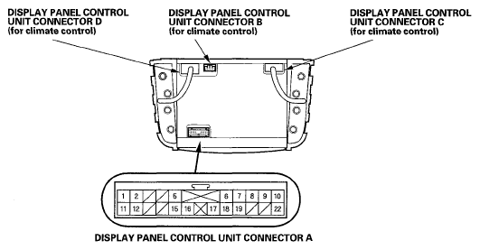
NOTE:
For the display panel control unit connectors C, and D, refer to the circuit diagram of climate control (see
CIRCUIT DIAGRAM
), and for the display panel control unit connector B and E, refer to the system description of navigation system (see
DIAGNOSTIC FUNCTION DIAGRAM
). DISPLAY PANEL CONTROL UNIT CONNECTORS
| Cavity |
Wire |
Connects to |
| A1 |
GRY |
Electrical compass unit |
| A2 |
LT GRN |
Electrical compass unit |
| A5 |
BLK |
Ground (G501) |
| A6 |
RED |
Dash lights brightness controller (LED) |
| A7 |
BLU |
Audio BUS+ (GA-NET) |
| A8 |
RED/BLK |
Light-on signal |
| A9 |
YEL/RED |
ACC (Main stereo power supply) |
| A10 |
WHT/RED |
Constant power |
| A11 |
PUR |
Electrical compass unit |
| A12 |
BRN |
Electrical compass unit |
| A15 |
RED/BLU |
Dash lights brightness controller (LED) |
| A16 |
ORN |
Audio unit (IMS 1) |
| A17 |
BLK |
Audio unit (IMS 0) |
| A18 |
GRY |
Audio BUS SH (GA-NET) |
| A19 |
PNK |
Audio BUS - (GA-NET) |
| A22 |
LT BLU |
Multiplex integrated control unit (B-CAN) |